Plate type heat exchanger for granular solid materials

A granular solid, material plate technology, applied in the direction of heat exchanger type, heat exchanger shell, indirect heat exchanger, etc., can solve the problems of plate failure, reduce output, unrealistic cleaning operation, etc., and achieve convenient disassembly operation. , The effect of prolonging the service life and avoiding repeated alternating loads

Active Publication Date: 2012-04-25
兰州节能环保工程有限责任公司 +1
View PDF10 Cites 5 Cited by
  • Summary
  • Abstract
  • Description
  • Claims
  • Application Information

AI Technical Summary

Problems solved by technology

However, due to the fact that the solid material flow will generate greater friction on the plates during movement, and some particles with large particle sizes and sharp edges will inevitably interact with the plates during the operation, so the patent stated The problem of early failure of individual plates due to local friction is prone to occur in the operation of heat exchangers
On the other hand, due to the uneven heat transfer of solid materials, it is inevitable that there will be local overheating during operation, which can easily cause local materials to stick due to overheating, resulting in the inability of the materials to flow according to the design requirements, and thus causing the materials to flow in the heat exchanger. The overall heat junction in the interior makes the heat exchanger unable to operate as a whole, which requires opening the heat exchange body of the patent to restore the operation of the equipment, and it is unrealistic and very difficult for the patented device to carry out the operation of the obstacle
In the actual production process, it is often necessary to increase the output during the peak production season and reduce the output during the off-season. However, the structure of the 98246396.0 patent cannot be applied to the requirements of different operating seasons because the heat exchange area is fixed.

Method used


Image

  • Plate type heat exchanger for granular solid materials
  • Plate type heat exchanger for granular solid materials
  • Plate type heat exchanger for granular solid materials

Examples


Embodiment Construction

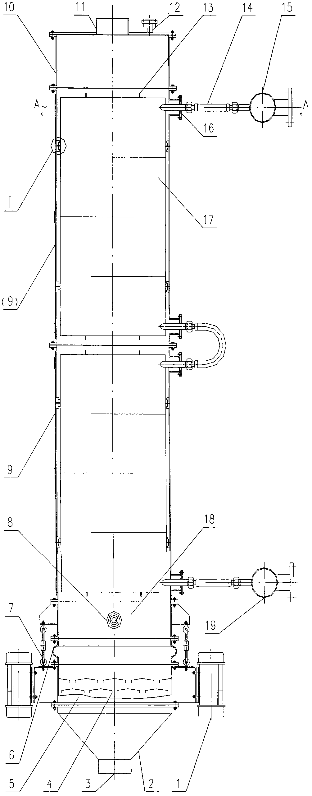
[0025] The whole device of the present invention will be explained below with reference to the embodiment of the accompanying drawings. In this embodiment, the structure of two heat exchange main bodies is adopted.

[0026] Depend on figure 1 It can be seen that the powdery solid material plate heat exchanger of the present invention consists of a feed bin 10, an upper and a lower heat exchanger main body 9 assembled in series from top to bottom, and an outlet disposed under the lower heat exchange main body 9. Silo composition. Among them, the heat exchange main body and the feeding bin, as well as the upper and lower heat exchange main bodies are connected and fixed by flanges. The heat exchange main body 9 is fixed with the discharge bin collection box 5 by adjusting the hook chain fixing mechanism 7. The discharge bin collection box 5 is provided with a measuring chamber 18, and the lower end of the silicone bellows 6 is connected to the vibration discharge bin. 2. Conne...


PUM


Abstract

The invention discloses a heat exchange device for granular solid materials or crystal materials which serve as heat exchange objects. In the heat exchange device, the cross sections of heat exchange main bodies are rectangular shells; heat exchange plates in which heat exchange medium flow channels are formed and a structure which is formed by granular solid material flow channels formed among all the heat exchange plates are arranged inside the rectangular shells at intervals; the heat exchange main bodies as well as the heat exchange main bodies and a material discharging cabin or a material feeding cabin in a material discharging device are fixedly connected through flanges; one surface of the rectangular shells of the heat exchange main bodies is combined with a neighboring surface through a hinge, and the surface is combined with another neighboring surface through a bolt and nut pair, so that the surface forms a movable door; one side, close to the heat exchange plates, of the movable door is provided with a strip-type pressing plate and a flexible pad which are fixed by screws; and during specific application, the heat exchange plates contacted with the flexible pad are tightly pressed against one another for constraint through the flexible pad.

Description

technical field [0001] The invention relates to a heat exchange device, in particular to a device in which the heat exchange object is a powdery solid or crystal substance. The present invention includes a heat exchanger main body, a feeding device, a vibrating unloading device, a temperature measuring device and a material level control device, wherein: the heat exchanger main body is arranged in a shell with a rectangular cross-section and its interior is arranged at intervals. The heat exchange plates of the heat medium flow channel and the powdery solid material flow channels formed between the heat exchange plates are formed. Background technique [0002] In modern industrial production activities, such as chemical fertilizers, cement, mineral powder, pharmaceuticals, food and other solid powder or uniform granular crystal industrial raw materials and their finished products require a large number of different degrees of heat exchange every day, and some products need t...

Claims


Application Information

Patent Timeline
Patent Type & Authority Applications(China)
IPC IPC(8): F28D9/00F28F9/26
Inventor 王生林张培洲马兆云邵珲张兵
Owner 兰州节能环保工程有限责任公司
Why Eureka
Try Eureka