Dynamic loading device for high-speed motorized spindle

A high-speed electric spindle and dynamic loading technology, which is applied in the testing of machine gears/transmission mechanisms, can solve problems such as the inability to simulate the influence of electric spindles, and achieve increased applicability and flexibility, authentic experimental data, and high loading accuracy. Effect

Active Publication Date: 2012-04-25
JILIN UNIV
View PDF6 Cites 35 Cited by
  • Summary
  • Abstract
  • Description
  • Claims
  • Application Information

AI Technical Summary

Problems solved by technology

[0004] The technical problem to be solved by the present invention is to overcome the problem that the existing technology cannot simulate the influence of dynamic high-frequency cutting force on the electric spindle, and to provide a dynamic loading device for high-speed electric spindle

Method used


Image

  • Dynamic loading device for high-speed motorized spindle
  • Dynamic loading device for high-speed motorized spindle
  • Dynamic loading device for high-speed motorized spindle

Examples


Embodiment Construction

[0021] The present invention is described in detail below in conjunction with accompanying drawing:

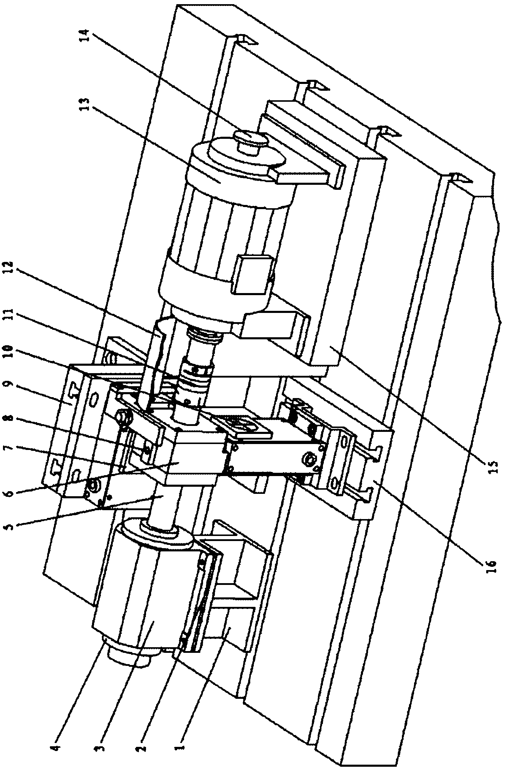
[0022] refer to figure 1 , The high-speed electric spindle dynamic loading device described in the present invention includes a supporting part, a loading part and an automatic control system.

[0023] 1. Support part

[0024] The supporting part includes a main shaft base, a radial loading backing plate 16 , an axial loading bracket 9 and a dynamometer base 15 .

[0025] The spindle base includes a spindle backing plate 1 , an adjusting gasket 2 and a clamping mechanism 3 . The spindle backing plate 1 is fixed on the horizontal iron with bolts, so that the measured high-speed electric spindle 4 can be axially adjusted along the longitudinal trapezoidal groove of the horizontal iron. By adjusting the structural size of the main shaft backing plate 1, the measured high-speed electric spindle 4 Make height adjustments. The radial loading backing plate 16 is a cuboid-shaped p...


PUM


Abstract

The invention discloses a dynamic loading device for a high-speed motorized spindle. The device comprises a supporting part and a loading part, wherein the supporting part comprises a spindle base, an axial loading bracket, a radial loading base plate and a dynamometer base. The spindle base comprises a spindle base plate, an adjusting base plate and a clamping mechanism. The loading part comprises a radial loading mechanism, an axial loading mechanism, a torque loading mechanism, a loading rod and a bearing unit. The torque loading mechanism comprises a power dynamometer and a high-speed spring tube coupling. The adjusting base plate and the clamping mechanism are overlapped on the spindle base plate and are fixedly connected with each other; the power dynamometer is fixed on the dynamometer base and is connected with the right end of the loading rod through the high-speed spring tube coupling; the left end of the loading rod is connected with the right end of a detected high-speed motorized spindle which is arranged in the clamping mechanism. The bearing unit is sleeved on the loading rod; the radial loading mechanism is arranged on the radial loading base plate and is positioned just below the bearing unit; and one end of the axial loading mechanism is arranged on the axial loading bracket, and the other end of the axial loading mechanism is in contact connection with the bearing unit.

Description

technical field [0001] The invention relates to a loading device, more precisely, the invention relates to a dynamic loading device for a high-speed electric spindle. Background technique [0002] The high-speed motorized spindle under test is a key functional component of high-speed CNC machine tools and a product of the rapid development of contemporary high-speed machining technology. It eliminates the transmission mechanism and is more precise in control, thereby improving the response speed and machining accuracy of the machine tool. At present, there are significant differences in the static, dynamic performance and reliability level of the domestically-made high-speed electric spindle compared with foreign countries. The improvement of machine performance plays a key role. To study the high-speed electric spindle under test, a dynamic loading device that can simulate the real working conditions of the high-speed electric spindle under test is needed, and on this basi...

Claims


Application Information

Patent Timeline
Patent Type & Authority Applications(China)
IPC IPC(8): G01M13/02
Inventor 杨兆军呼烨陈菲李国发申桂香王凯朱岩王微
Owner JILIN UNIV
Why Eureka
Try Eureka