Constant-time control circuit for switch type adjuster as well as switch type adjuster using control circuit

A constant time, control circuit technology, applied in the direction of adjusting electrical variables, control/regulation systems, instruments, etc., can solve problems such as component damage, output voltage overshoot, and slow response to transient changes, so as to avoid fluctuations, fast transient Dynamic response, improve the effect of transient response speed

Active Publication Date: 2014-03-12
SILERGY SEMICON TECH (HANGZHOU) CO LTD
View PDF5 Cites 0 Cited by
  • Summary
  • Abstract
  • Description
  • Claims
  • Application Information

AI Technical Summary

Problems solved by technology

[0010] Visible, using as Figure 1A The DC-DC converter shown in the constant on-time control scheme responds very slowly to the transient change of the load, and will produce an overshoot of the output voltage, which will cause damage to the components in the circuit

Method used


Image

  • Constant-time control circuit for switch type adjuster as well as switch type adjuster using control circuit
  • Constant-time control circuit for switch type adjuster as well as switch type adjuster using control circuit
  • Constant-time control circuit for switch type adjuster as well as switch type adjuster using control circuit

Examples


Embodiment Construction

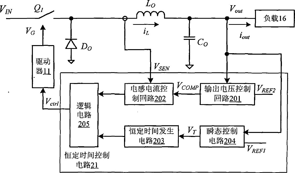
[0060] refer to figure 2 It is the principle box diagram of the concentrated time control circuit of the constant time control circuit according to a concentrated time control circuit of a switch -type regulator of the present invention.

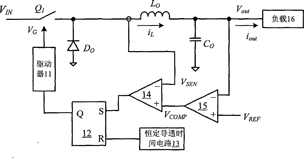
[0061] In this embodiment, the working principle of the constant time control circuit is explained by the pressure -drop -type switching regulator as an example.Switching device Q 1 , Diodes d 0 , Inductor L 0 And output capacitance C 0 The power -level circuit that forms a one -voltage topological structure, the input terminal receiving input voltage V IN The output end connection one load 16.

[0062] The constant time control circuit 21 includes a transient control circuit 204, and its receiving output voltage V out And the first voltage benchmark V REF1 To determine the transient change on the load of the switch -type regulator.

[0063] When the load of the switch -type regulator has a transient change, the transient control circuit 204 gen...


PUM


Abstract

In one embodiment, a controlling method for a switching regulator, can include: (i) detecting an output voltage and an inductor current of the switching regulator; (ii) determining if there is a transient change on a load of the switching regulator by using the output voltage and a first reference voltage; (iii) generating a control signal using the output voltage, the inductor current, and a second reference voltage; (iv) controlling a switch of the switching regulator to maintain the output voltage substantially constant when no transient change is determined on the load; and (v) deactivating the control signal to keep the inductor current changing along with a variation tendency of an output current of the switching regulator when a transient change is determined on the load.

Description

Technical field [0001] The invention involves a power technology, and more specifically, it involves a switch -type regulator that uses a constant time control scheme. Background technique [0002] The switching power supply consists of two parts: power -level circuit and control circuit.The function of the control circuit is to regulate the turnover system in the switch system in the power -level circuit when the input voltage, internal parameters and external load changes are changed to keep the output voltage or output current of the switching power supply constant.Therefore, in the design of the switching power supply, the selection and design of the control method is very important for the performance of the switching power supply.Different detection signals and different control circuits have different control effects. [0003] The control method of the switching power supply can be divided into fixed frequency control and frequency conversion control.Frequency control is t...

Claims


Application Information

Patent Timeline
Patent Type & Authority Patents(China)
IPC IPC(8): H02M3/00
CPCH02M2003/1566H02M3/156H02M3/157H02M3/1566
Inventor 陈伟
Owner SILERGY SEMICON TECH (HANGZHOU) CO LTD
Why Eureka
Try Eureka