
Clock converting and locking method and circuit

A clock conversion and locking circuit technology, applied in the field of communication and navigation, can solve the problems of difficult frequency locking, complex clock locking multiple relationship, frequency limitation of frequency division and multiplication circuit, and complicated circuit.

Active Publication Date: 2013-05-15
SHANGHAI ENG CENT FOR MICROSATELLITES
View PDF1 Cites 0 Cited by
  • Summary
  • Abstract
  • Description
  • Claims
  • Application Information

AI Technical Summary

Problems solved by technology

[0005] The technical problem to be solved by the present invention is to provide a clock conversion and locking method and its circuit, which solves the frequency limitation of the frequency division and multiplication circuit in the traditional clock conversion and locking design and the relatively complicated problems of the circuit, especially for two clocks The complex relationship of locking multiples may lead to the problem that the frequency is difficult to lock

Method used


Image

  • Clock converting and locking method and circuit
  • Clock converting and locking method and circuit

Examples


Embodiment Construction

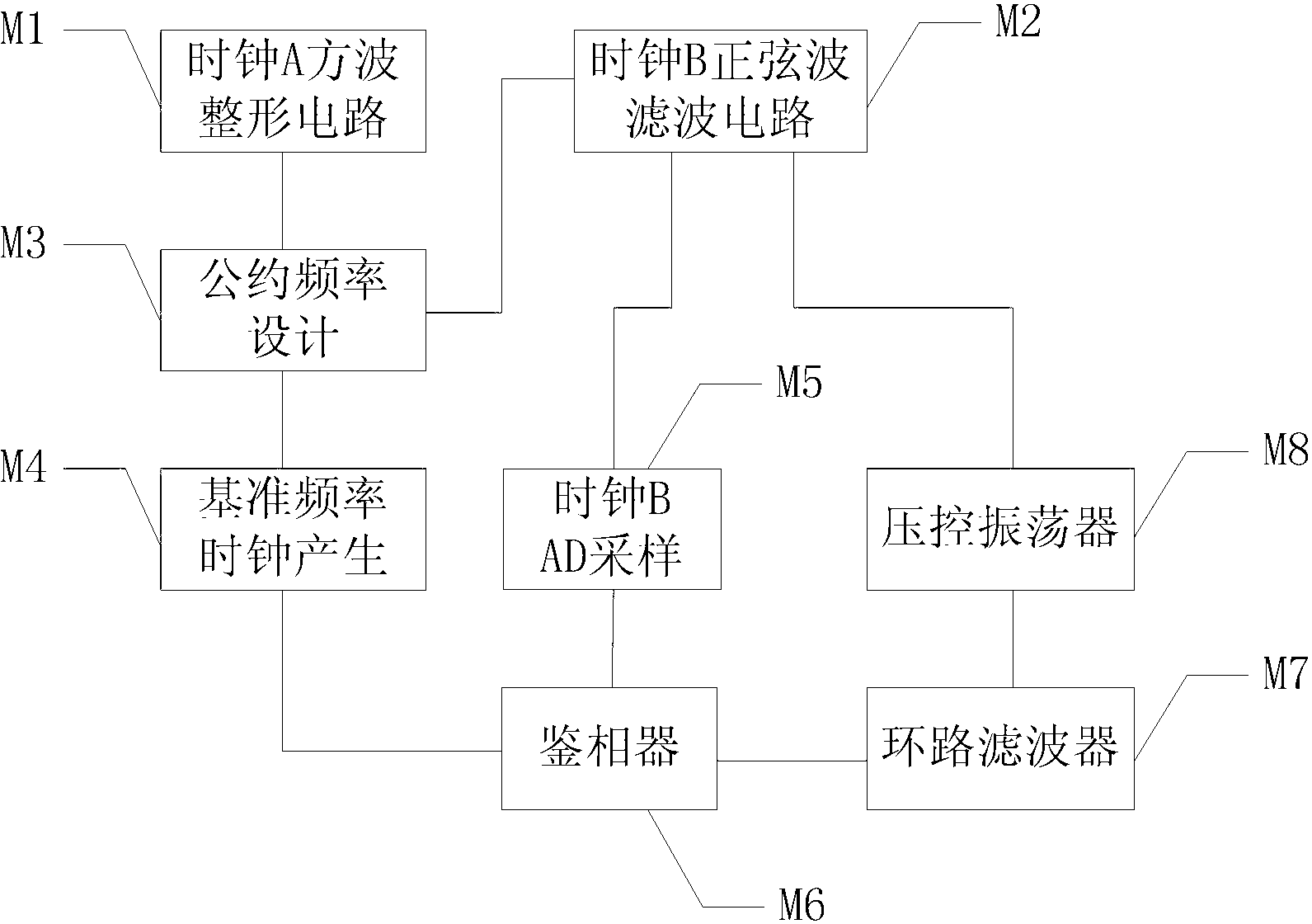
[0016] The specific implementation of the clock conversion and locking method and its circuit provided by the present invention will be further described in detail below in conjunction with the accompanying drawings.

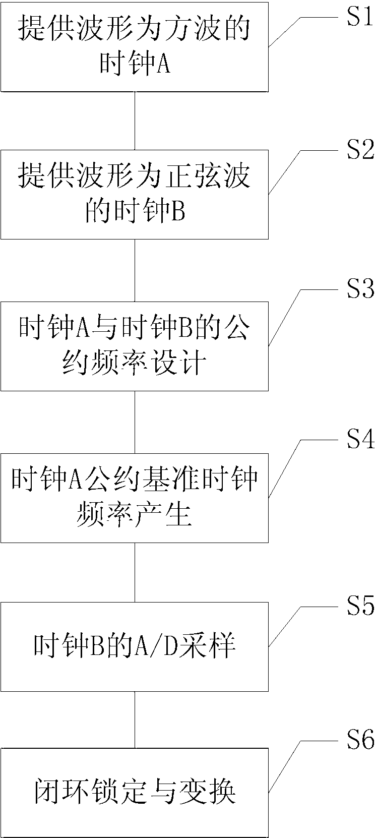
[0017] figure 1 The described flow chart of the clock conversion and locking method includes: Step S1: providing a clock A whose waveform is a square wave; Step S2: providing a clock B whose waveform is a sine wave; Step S3: designing the conventional frequency of clock A and clock B; S4: clock A generates a reference clock frequency; step S5: A / D sampling of clock B; step S6: closed-loop locking and conversion.

[0018] Step S1: Provide a clock A with a square wave waveform. If the clock A is not a square wave, you can use an op amp or a diode to perform square wave shaping on the clock A as the input clock, and shape it into a digital clock signal to reduce clock edge jitter. ; If the output of clock A is a square wave signal, it can be directly used as an in...


PUM


Abstract

The invention discloses a clock converting and locking method, comprising the steps of: providing a clock A with square wave and a clock B with sine wave; computing a frequency common divisor of the frequency values of the two clocks to serve as a common division frequency for the conversion of the two clocks; obtaining the common division reference clock frequency of the clock A by using a counting frequency-dividing way; performing A / D (Analog to Digital) sampling to the clock B to obtain the sampling frequency of the clock B by using the common division reference clock frequency as a parameter; using the common division reference clock frequency and the sampling frequency as the parameters to design a phase-locked loop; accessing the output frequency of the phase-locked loop into the frequency control end of the clock B, thereby completing the closed-loop work of the whole system; the lock and the conversion of the clock A to the clock B are implemented under the circumstance of requiring no frequency multiplication to a high multiple frequency.

Description

technical field [0001] The invention relates to the field of communication and navigation, in particular to a clock conversion and locking method and a circuit thereof. Background technique [0002] In communication and navigation systems, in order to achieve frequency conversion and locking, reference clocks, radio frequency clocks or other clocks are commonly used at present, and the frequency conversion methods of frequency multiplication or frequency division are used to obtain various frequencies required by the equipment. Through design Appropriate locking components to achieve. [0003] The phase-locked loop technology can be used to achieve frequency multiplication, output a stable frequency multiplication clock, and the phase relationship between the output clock phase and the input clock phase is constant, and in some designs, this phase relationship can also be adjusted according to system needs. But the disadvantage of this method is that the phase-locked loop h...

Claims


Application Information

Patent Timeline
Patent Type & Authority Patents(China)
IPC IPC(8): H03L7/18H03L7/099
Inventor 帅涛梁旭文张军易争荣刘亚欢黄康聂伟龚文斌任前义赵笙罡刘静刘彬胡伟圣洪霞
Owner SHANGHAI ENG CENT FOR MICROSATELLITES
Learn More