
Thermal head, thermal printer and manufacturing method for the thermal head

A thermal head and heating resistor technology, applied in printing and other directions, can solve the problems of insufficient performance and high thermal insulation performance, and achieve the effects of reducing power consumption, prolonging duration, and inhibiting thermal diffusion

Inactive Publication Date: 2012-05-02
SEIKO INSTR INC
View PDF7 Cites 0 Cited by
  • Summary
  • Abstract
  • Description
  • Claims
  • Application Information

AI Technical Summary

Problems solved by technology

Therefore, in the conventional thermal head, heat is dissipated from the heat generating resistor through the electrode part in the plane direction of the upper board substrate, and thus there is a problem that the high thermal insulation performance due to the cavity part cannot be fully exhibited.

Method used


Image

  • Thermal head, thermal printer and manufacturing method for the thermal head
  • Thermal head, thermal printer and manufacturing method for the thermal head
  • Thermal head, thermal printer and manufacturing method for the thermal head

Examples


no. 1 approach

[0043] Next, the thermal head, the printer, and the method of manufacturing the thermal head according to the first embodiment of the present invention will be described with reference to the drawings.

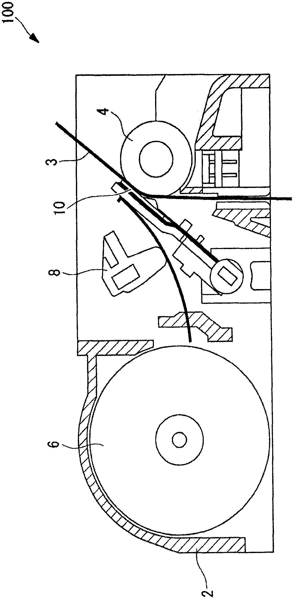
[0044] A thermal printer (printer) 100 according to this embodiment includes a main body frame 2, a platen roller 4 arranged horizontally, a thermal head 10 arranged to face the outer peripheral surface of the platen roller 4, A paper feeding mechanism 6 that conveys a printing object such as thermal paper (thermal recording medium) 3 to and from the thermal head 10 and a pressing mechanism 8 that presses the thermal head 10 against the thermal paper 3 with a predetermined pressing force.

[0045] The thermal paper 3 and the thermal head 10 are pressed against the platen roller 4 by the action of the pressing mechanism 8 . Thus, the load of the platen roller 4 is applied to the thermal head 10 via the thermal paper 3 .

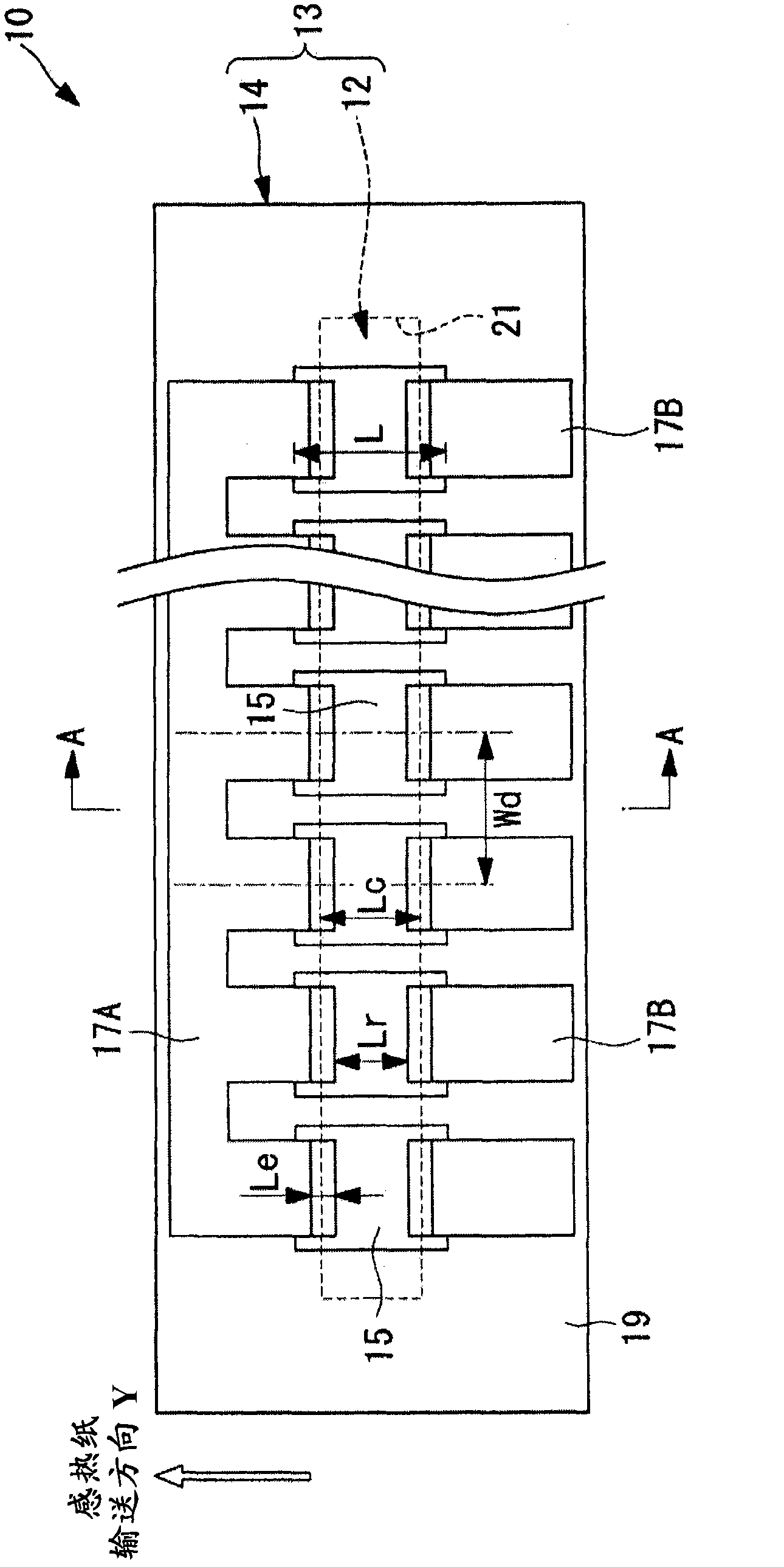
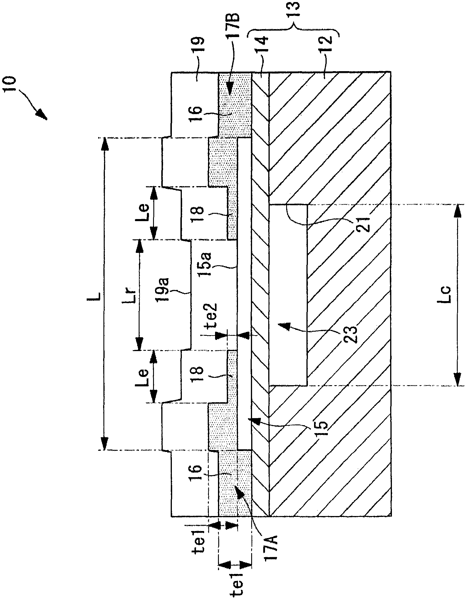
[0046] Such as figure 2 and image 3 As shown, the t...

no. 2 approach

[0098] Next, the thermal head, the printer, and the method of manufacturing the thermal head according to the second embodiment of the present invention will be described.

[0099] The thermal head 110 involved in this embodiment is as Figure 11 As shown, the electrode portions 117A, 117B include the low thermal conductivity portion 118 made of a material having a lower thermal conductivity than other regions and a resistance value lower than that of the heating resistor 15 in the region facing the hollow portion 23 , which is similar to that of the first embodiment. different ways. Hereinafter, parts common to those of the thermal head 10 , the thermal printer 100 , and the manufacturing method and structure of the thermal head according to the first embodiment are denoted by the same reference numerals and descriptions thereof are omitted.

[0100] The electrode portions 117A, 117B have a substantially uniform film thickness over the entirety. The part where the electrode...


PUM


Abstract

A thermal head (10) includes: a substrate main body (13) including a flat plate-shaped support substrate (12) and a flat plate-shaped upper substrate (14) which are bonded to each other in a stacked state; a heating resistor (15) formed on a surface of the upper substrate (14); and a pair of electrodes (17A, 17B) connected to both ends of the heating resistor (15), respectively, for supplying power to the heating resistor (15), in which the substrate main body (13) includes a cavity portion (23) in a region opposed to the heating resistor (15) at a bonding portion between the support substrate (12) and the upper substrate (14), and at least one of the electrodes (17A, 17B) includes a thin portion (18) in a region opposed to the cavity portion (23), the thin portion being thinner than other regions of the electrodes (17A, 17B).

Description

technical field [0001] The invention relates to a thermal head, a thermal printer and a manufacturing method of the thermal head. Background technique [0002] Conventionally, thermal heads used in thermal printers are widely known (for example, refer to Patent Document 1). In the thermal head described in Patent Document 1, a plurality of heating resistors are formed on a laminated substrate of a support substrate and an upper substrate, and by supplying power to a pair of electrode parts connected to the heating resistors, the heating resistors can be made to generate heat. Printing on thermal recording media, etc. [0003] In this thermal head, a cavity is formed at a position facing the heating resistor in a joint portion between the support substrate and the upper substrate. The cavity functions as a heat insulating layer with low thermal conductivity, thereby reducing heat transferred from the heating resistor to the support substrate via the upper substrate, improvi...

Claims


Application Information

Patent Timeline
Patent Type & Authority Applications(China)
IPC IPC(8): B41J2/335B41J2/32
CPCB41J2/33585B41J2/3354B41J2/3351Y10T29/49002
Inventor 师冈利光顷石圭太郎东海林法宜三本木法光
Owner SEIKO INSTR INC
Learn More