Continuous resistance-increasing deforming anchor rod

A technology of anchor rods and connecting rods, which is applied in the installation of anchor rods, mining equipment, earthwork drilling and mining, etc. It can solve problems such as damage accidents, underground engineering instability, and unstable performance, and achieve increased working resistance, stable performance, and structural stability. simple effect

Inactive Publication Date: 2012-05-02
SHANDONG UNIV OF SCI & TECH
View PDF9 Cites 14 Cited by
  • Summary
  • Abstract
  • Description
  • Claims
  • Application Information

AI Technical Summary

Problems solved by technology

When the deformation of the surrounding rock is large and exceeds the range that the anchor can bear, it will lead to the failure of the anchor, and then cause the instability and destruction of the underground engineering.
The bolts currently used have small deformability, unstable performance, difficult processing, cannot adapt to the characteristics of large deformation, and cannot meet the support needs of modern underground engineering.

Method used


Image

  • Continuous resistance-increasing deforming anchor rod
  • Continuous resistance-increasing deforming anchor rod
  • Continuous resistance-increasing deforming anchor rod

Examples


Embodiment 1

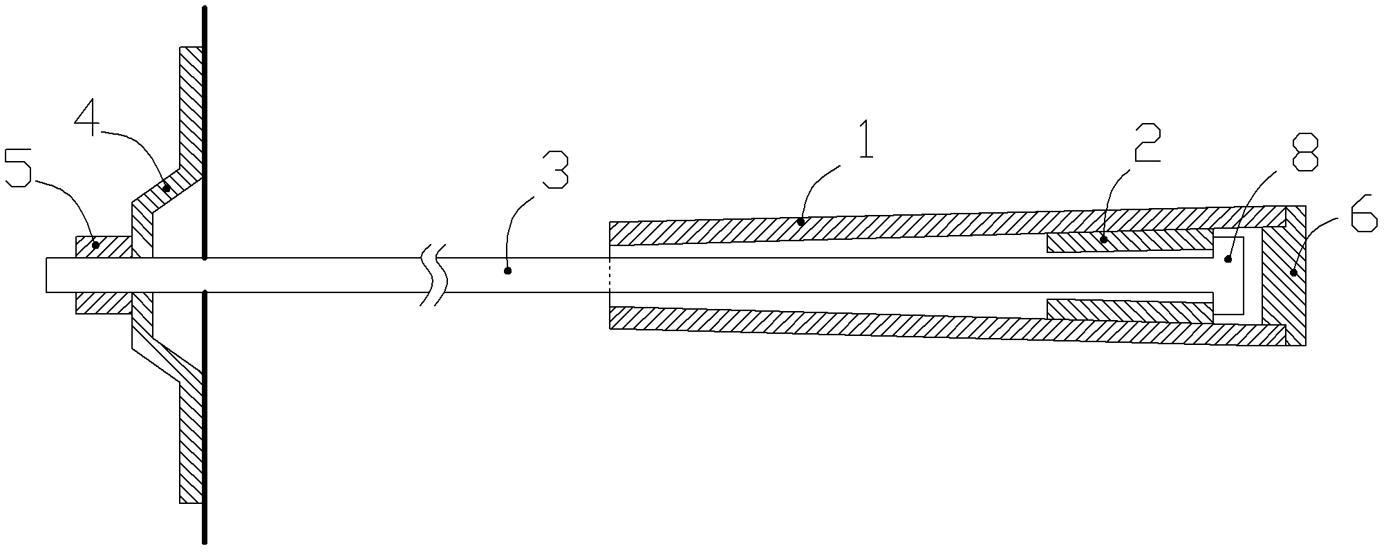
[0027] combine Figure 1 to Figure 5 , a continuous resistance-increasing deformation anchor rod, including a friction sleeve 1, a shrinkable member 2, a fixed tie rod 3, a tray 4 and a nut 5.

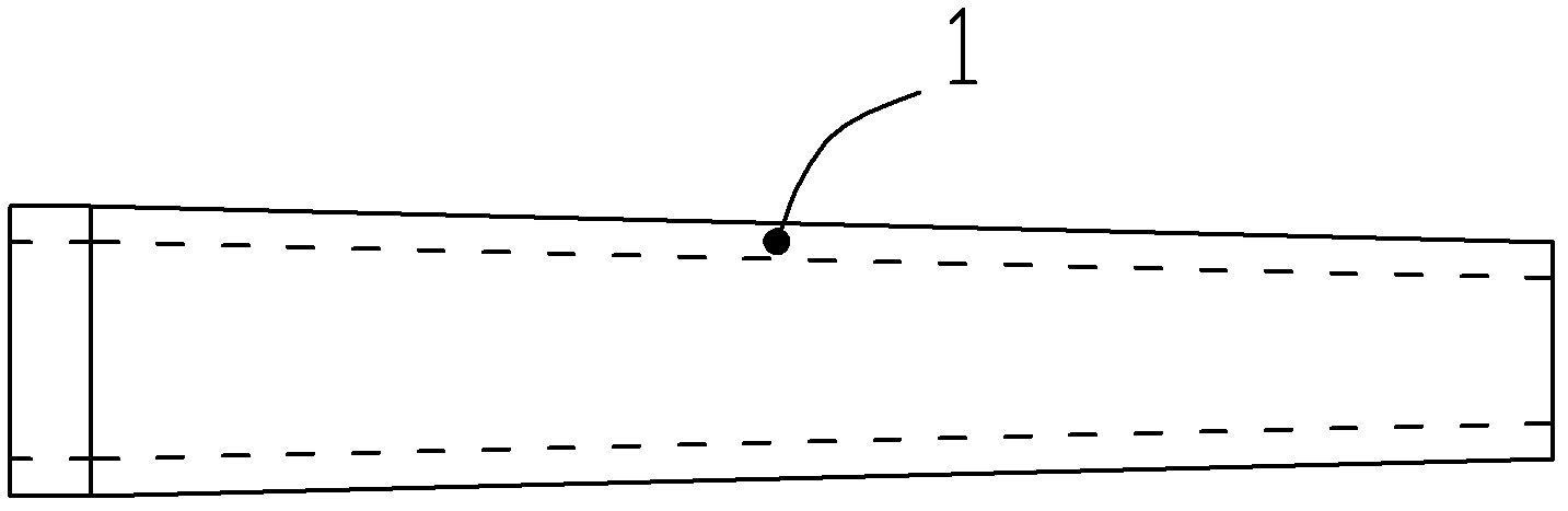
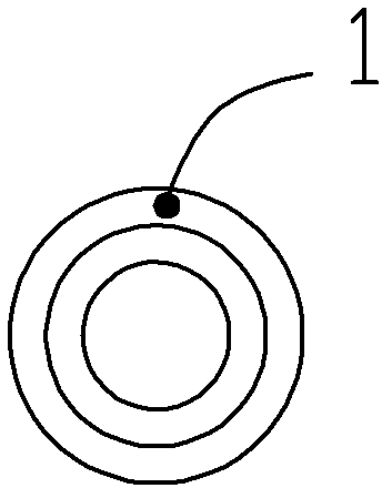
[0028] The inner diameter of the above-mentioned friction sleeve gradually decreases from one end of the sleeve to the other end. Such as the selection of frustum-shaped or conical steel pipes. In addition to the conventional smooth surface structure, the inner and outer pipe walls of the above-mentioned friction sleeve can also adopt such a preferred method, that is, the inner pipe wall, or the inner pipe wall and the outer pipe wall are provided with circumferential ribs, Used to increase the coefficient of friction. A casing end cap 6 is provided at the nozzle end of the above-mentioned friction casing with a large inner diameter. The casing end cap and the nozzle end can be threadedly connected, and a wedge-shaped or tapered tip can be selectively arranged on the outside of the c...

Embodiment 2

[0031] combine Figure 6 , a continuous resistance-increasing deformation anchor rod, including a friction sleeve 1, a shrinkable member 2, a fixed tie rod 3, a tray 4 and a nut 5.

[0032] The inner diameter of the above-mentioned friction sleeve gradually decreases from one end of the sleeve to the other end. Such as the selection of frustum-shaped or conical steel pipes. In addition to the conventional smooth surface structure, the inner tube wall of the above-mentioned friction sleeve can also adopt such a preferred method, that is, the inner tube wall is provided with circumferential ribs to increase the coefficient of friction. The nozzle end of the above-mentioned friction casing with a large inner diameter is provided with a casing end plug 6 and the casing end plug and the nozzle end can be connected by threads.

[0033] The above-mentioned shrinkable member, the shrinkable member is a tubular structure, nested in the friction sleeve, the outer diameter of the shrin...


PUM


Abstract

The invention discloses a continuous resistance-increasing deforming anchor rod, which is characterized by comprising a friction casing, a collapsible member and a fixing pull rod, wherein the inner diameter of the friction casing gradually becomes smaller from one end of the casing to the other end of the casing; the collapsible member is a tubular structure, and is nested in the friction casing, the outer diameter of the collapsible member gradually becomes smaller from one end to the other end of the member, and the outer wall of the collapsible member is kept contact with the inner wall of the friction casing; and one end of the fixing pull rod is connected with the collapsible member, and the fixing pull rod is led out from the small inner-diameter orifice end of the friction casing. When surrounding rock is largely deformed, the invention can be extended under tension without damage, also can continuously increase working resistance, and also can constantly absorb the energy of surrounding rock deformation during the process. In addition, the invention has the characteristics of simple structure, easy manufacturing, stable performance and the like.

Description

technical field [0001] The invention relates to a support bolt used in underground projects such as water conservancy and hydropower projects, tunnel projects, and mine projects, and in particular to a continuous resistance-increasing high-strength bolt capable of continuous deformation without damage. Background technique [0002] In the support of underground projects such as water conservancy and hydropower projects, tunnel projects, and mining projects, bolts are a kind of support equipment that is widely used. With the continuous increase of mining depth and the construction of large-scale underground engineering, the geological conditions are becoming more and more complex, and the surrounding rock often shows the characteristics of large deformation. When the deformation of the surrounding rock is large and exceeds the range that the bolt can bear, it will lead to the failure of the bolt, and then cause the instability and destruction of the underground engineering. ...

Claims


Application Information

Patent Timeline
Patent Type & Authority Applications(China)
IPC IPC(8): E21D21/00
Inventor 蒋宇静吴学震王刚文志杰陈连军王春光
Owner SHANDONG UNIV OF SCI & TECH
Why Eureka
Try Eureka