Pressure yielding mechanism

A technology of sheet pressing and rod body, which is used in mining equipment, earth-moving drilling, bolt installation, etc., can solve the problems of low elongation rate of ordinary bolts, support resistance cannot be adjusted with the deformation of bolts, and can not meet the needs of large deformation. , to achieve the effect of good support and pressure, good effect and flexible change

Active Publication Date: 2017-05-24
HUNAN UNIV
View PDF6 Cites 0 Cited by
  • Summary
  • Abstract
  • Description
  • Claims
  • Application Information

AI Technical Summary

Problems solved by technology

[0003] The purpose of the present invention is to provide a pressure relief mechanism, which is used in bolts to solve the problems of low elongation of ordinary bolts, support resistance that cannot be adjusted with the deformation of the bolt, and failure to meet the needs of large deformations such as roadway surrounding rock slopes.

Method used


Image

  • Pressure yielding mechanism
  • Pressure yielding mechanism
  • Pressure yielding mechanism

Examples


Embodiment Construction

[0032] The present invention will be described in further detail below in conjunction with the accompanying drawings.

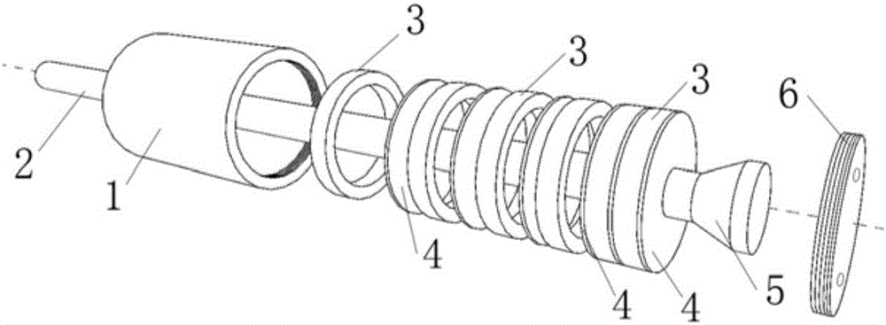
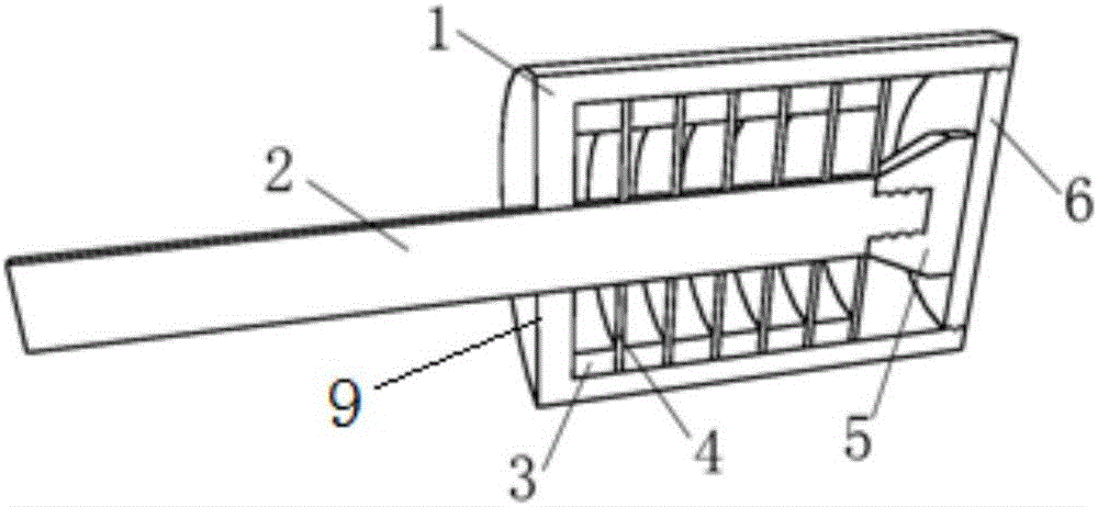
[0033] Such as figure 1 The pressure relief mechanism shown is composed of a shell 1, a rod body 2, an annular gasket 3, a pressure relief sheet 4, a cutting head 5, and a sealing cover 6.

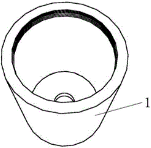
[0034] The shell 1 is a metal cylinder with a bottom plate of a certain thickness and strength, and its upper part is provided with threads, which can be closed with a sealing cover 6 . There is a circular hole in the center of the cylinder bottom plate, and the diameter of the hole is slightly larger than the diameter of the rod body 2, so that the rod body 2 can slide up and down in the circular hole. The shell 1 has sufficient strength to ensure that the deformation of the anchor rod is negligible during the stress process.

[0035] The rod body 2 is a common anchor rod in engineering, such as threaded steel, round steel, etc., and the selection of its diameter and m...


PUM


Abstract

The invention discloses a pressure yielding mechanism comprising a shell and a rod body, wherein one end of the rod body is protruded outwards to form a shearing head, two or more pressure yielding plates are fixed in the shell, through holes through which the rod body passes to clamp the shearing head are formed in the pressure yielding plates. An anchor rod produced by using the pressure yielding mechanism provided by the invention can be prolonged by stretching when surrounding rock of a roadway or a side slope deforms largely, an adjustable work resistance is provided along with the deformation and prolongation of the anchor rod, the work resistance can be increased and can also be decreased so as to be capable of changing flexibly, and can also be fully coordinated with the deformation state of the surrounding rock of the roadway or the side slope, and thus a good supporting and pressure yielding effect is provided.

Description

technical field [0001] The invention relates to a pressure relief mechanism, in particular to a bolt pressure relief mechanism suitable for roadways, side slopes, tunnels and other fields. Background technique [0002] In mining or tunnel engineering, the deformation energy of the surrounding rock may be large, and part of the deformation of the surrounding rock is uncontrollable deformation. For this part of the deformation, it should be allowed to occur instead of supporting, so that its energy Partial release and stress redistribution can make full use of the bearing capacity of the surrounding rock itself and save support costs. The rest will need to be braced to prevent collapse. The deformation of the surrounding rock develops gradually, but the support is generally carried out immediately after excavation. If an ordinary bolt is used for support, since it cannot produce excessive deformation, the support force may be too large in the later stage, and the anchor body...

Claims


Application Information

Patent Timeline
Patent Type & Authority Applications(China)
IPC IPC(8): E21D21/00
Inventor 罗宏陈仁朋洪鹏云孙和美林星涛
Owner HUNAN UNIV
Why Eureka
Try Eureka