
Clutch controlling device

A technology of clutch control and clutch, which is applied in clutches, friction clutches, electric clutches, etc., can solve the problems of unadjustable separation cylinders that are not sufficiently reliable, have many components, complicated steps, and be careful enough, so as to improve the performance of assembly operations and Maintenance performance, maintenance control performance, cost reduction effect

Inactive Publication Date: 2012-05-02
优尼邦斯股份有限公司
View PDF3 Cites 11 Cited by
  • Summary
  • Abstract
  • Description
  • Claims
  • Application Information

AI Technical Summary

Problems solved by technology

[0012] However, when air is mixed in the clutch fluid, such a non-adjustable release cylinder used as an actuator of an automatic clutch cannot operate sufficiently reliably, requiring troublesome steps and sufficient care during assembly and maintenance, and There is a problem that the cost of the automatic clutch increases due to the many and complicated components including the hydraulic circuit
[0013] In order to avoid this problem, it is proposed that the automatic clutch adopts an electric actuator, but in this case, there is the following problem: it is necessary to consider the stroke variation of the clutch release mechanism when the clutch plate is worn, that is, to always detect the clutch relative to the clutch. The change of the contact point of the fork travel to control the clutch

Method used


Image

  • Clutch controlling device
  • Clutch controlling device
  • Clutch controlling device

Examples


Embodiment Construction

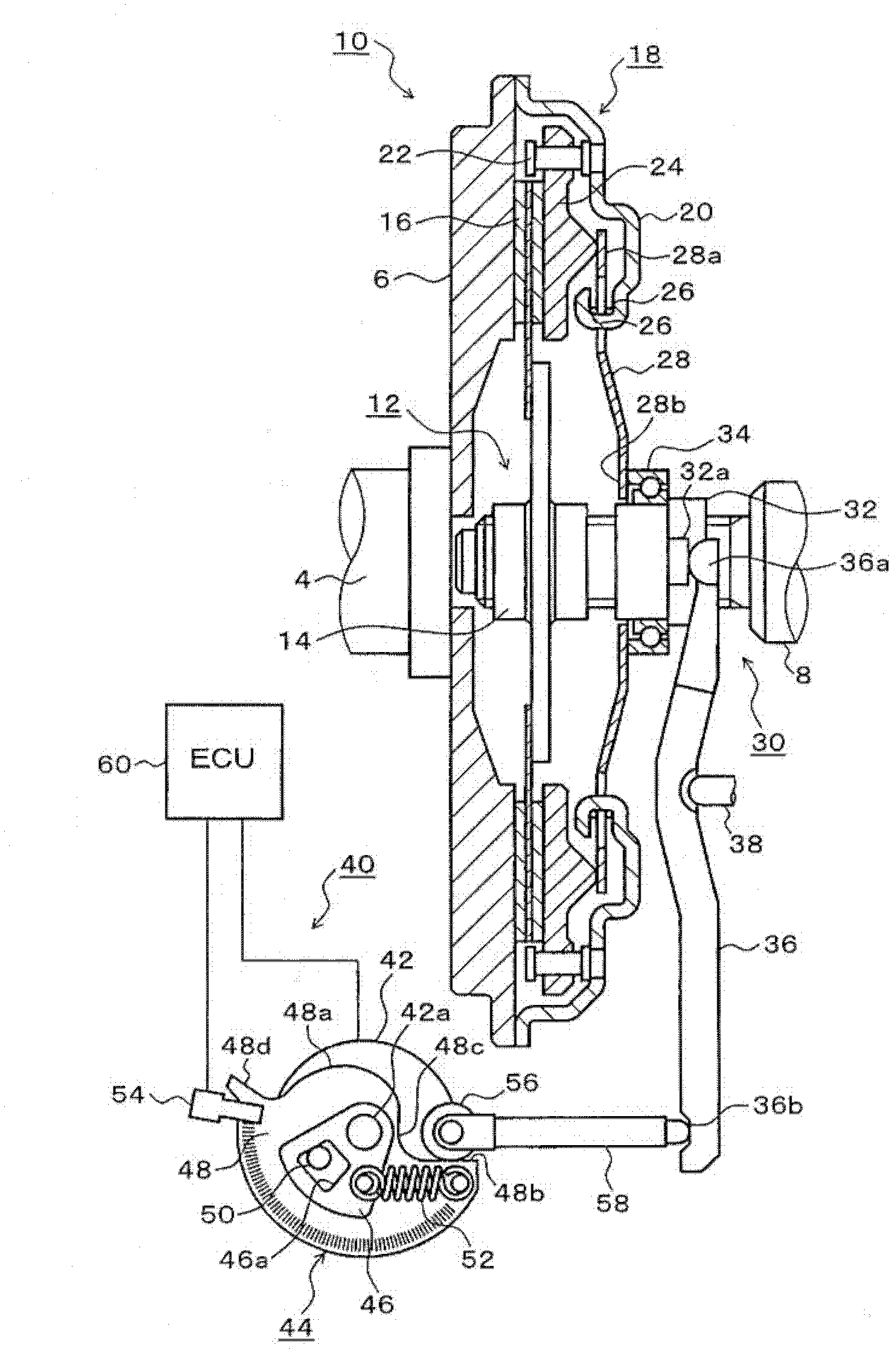
[0047] figure 1 It is an explanatory diagram showing an embodiment of a clutch provided with the clutch control device of the present invention, and shows a state in which the clutch is engaged when the clutch plate is a new product (not worn out).

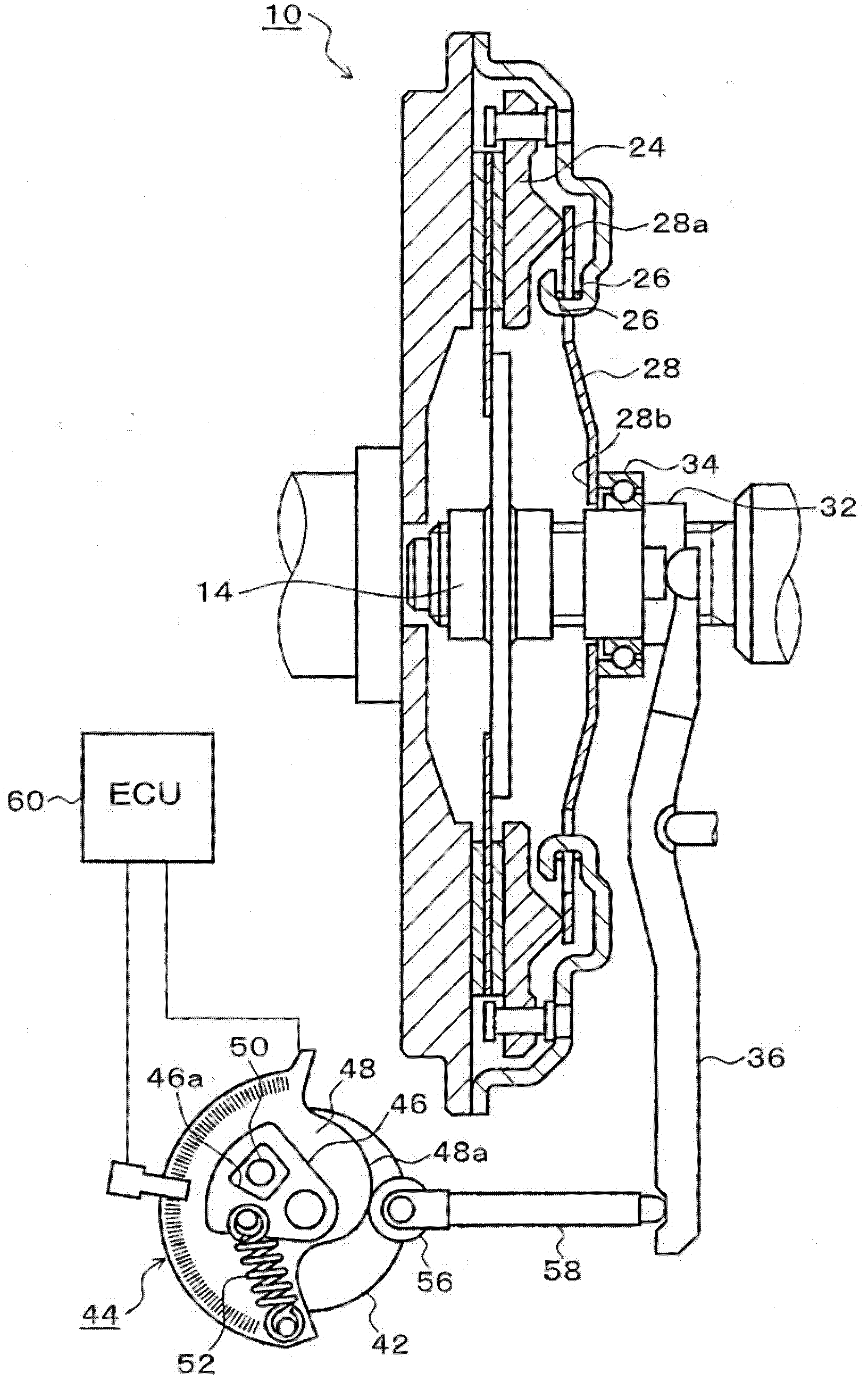
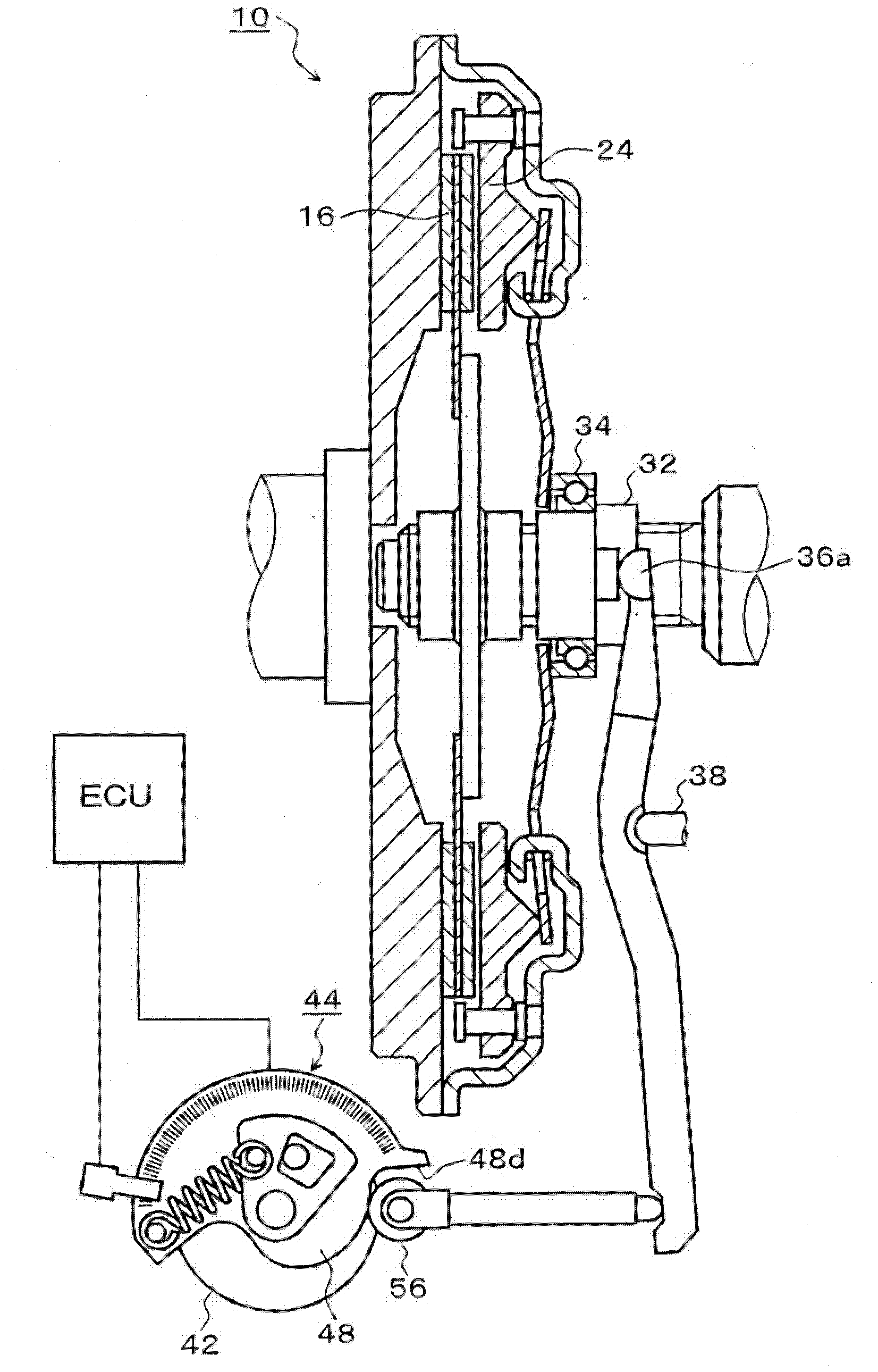
[0048] exist figure 1 Among them, the clutch 10 is a device that cuts off or engages the torque transmission from the flywheel 6 that rotates together with the engine output shaft 4 to the transmission input shaft 8. and the clutch control device 40.

[0049] The clutch plate assembling part 12 has the clutch hub 14 splined to the end portion of the transmission input shaft 8 and the clutch disc 16 provided on the clutch hub 14, and the clutch plate assembling part 12 can be moved along the axial direction of the transmission input shaft 8. Advance and retreat movements.

[0050] The clutch cover assembly part 18 has: a clutch cover 20 that rotates integrally with the flywheel 6; a pressure plate 24 that can move in the axial...


PUM


Abstract

A clutch controlling device is provided with: a motor (42); a cam (44), which is actuated by the motor (42), changes a clutch from a connected state to a disconnected state when moved forward from an initial position to a disconnection position, and changes the clutch to the connected state when moved backward from the disconnection position to the initial position; a roller (56), which transmits displacement of the cam (44) to a release fork (36); and an ECU (60), which moves the cam (44) forward after moved backward to a save position, sets a position at which load to a clutch release mechanism via the roller (56) is started as the initial position of the cam (44), and appropriately controls disconnection / connection and transmitted torque of the clutch (10) based on the set initial position.

Description

technical field [0001] The present invention relates to a clutch control device for operating a clutch disengagement mechanism by using an actuator, and particularly relates to detecting the start position of the disengagement action caused by the wear of the clutch plate, so as to properly perform disengagement and engagement of the clutch and control of the transmission torque technology. Background technique [0002] As a transmission for a vehicle, there is an automatically controlled manual transmission (AMT: Automatic Mechanical Transmission) that performs a shift operation using an actuator. An automatic clutch is used in an AMT vehicle equipped with such a transmission, which synchronizes the friction clutch device (hereinafter referred to as "clutch") provided between the engine and the transmission with the speed change operation of the transmission. The actuator cuts and engages automatically. [0003] In this AMT vehicle, a method of detecting the acceleration ...

Claims


Application Information

Patent Timeline
IPC IPC(8): F16D13/58F16D13/75
CPCF16D2500/50251F16D2500/50236F16D48/064F16D2500/5023F16D2500/1025F16D2500/10431F16D2023/123F16D23/12F16D2500/3022F16D28/00F16D2500/3026F16D2500/70235F16D2500/70252F16D2500/70418F16D2500/7101
Inventor 加藤忠彦山内义弘
Owner 优尼邦斯股份有限公司
Learn More