Check patentability & draft patents in minutes with Patsnap Eureka AI!

Head tracking system with improved head rotation detection

A head tracking, head technology used in radio wave measurement systems, stereo systems, direction finders using electromagnetic waves, etc.

Active Publication Date: 2016-07-06
HARMAN BECKER AUTOMOTIVE SYST
View PDF4 Cites 0 Cited by
  • Summary
  • Abstract
  • Description
  • Claims
  • Application Information

AI Technical Summary

Problems solved by technology

Only small head rotations of roughly + / - 20° can be detected with the geometry used in this patent application

Method used


Image

  • Head tracking system with improved head rotation detection
  • Head tracking system with improved head rotation detection
  • Head tracking system with improved head rotation detection

Examples


Embodiment Construction

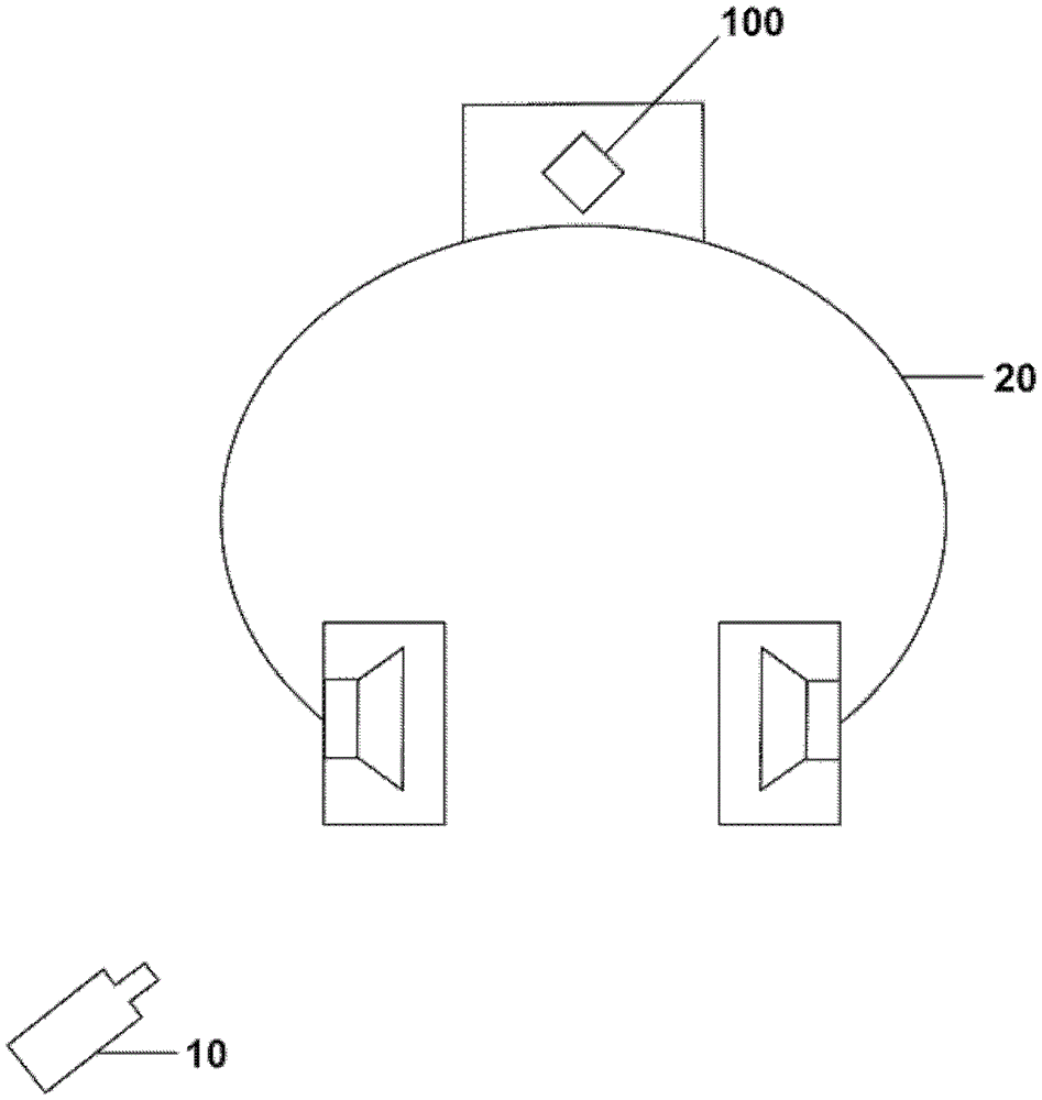
[0022] exist figure 1 A head tracking system is schematically shown in . The head tracking system includes one or more light sources 10 emitting light to a position sensitive device 100 mounted on the headset 20 . The light source 10 may be a light emitting diode (LED), which emits light in a predetermined frequency range, such as pulsed infrared rays. In order not to disturb the user wearing the headset 20, the infrared frequency range may be used. As referenced below Figure 2 to Figure 4 To explain in further detail, the light emitted by the LED 10 generates a light spot on the position sensitive device 100 . The position of the light spot on the position sensitive device is used to determine the position of the head of the user wearing the headset. The LED 10 can be arranged at a fixed position and can send light in the direction of the user wearing the headset. figure 1 The system shown in may be part of an entertainment system for the rear seat of a vehicle, in whic...


PUM


Abstract

The present application relates to a head tracking system for determining the position of a user's head, the system comprising a light source (10) emitting light onto a rectangular position sensitive device (100) disposed on a support member (200). The light emitted by the light source generates a light spot on the position sensitive device, and a head position determination module (170) is provided that uses the position of the light spot on the position sensitive device to determine the position of the head, wherein the support member (200) is designed to The position sensitive device (100) is supported in such a way that rotation of the head causes an angular displacement of the light spot towards the rectangular position sensitive device.

Description

technical field [0001] The present application relates to a head tracking system for determining the position of a user's head, and to an audio system using the head tracking system to generate virtual surround sound for said user. Background technique [0002] Head tracking systems are known which detect different types of head movements. For example, a gyroscope is used to detect the rotation of the head about the longitudinal axis of the head (ie at head level). Angular acceleration is detected using such a gyroscope. [0003] EP2012170A1 discloses a head tracking system in which position sensitive devices and light sources such as LEDs are used to calibrate out deviations occurring in gyroscopes. Only small head rotations of roughly + / - 20° can be detected with the geometry used in this patent application. Using an embodiment as described in EP2012170A1 it is not possible to determine the position of the head using only one single position sensitive device within a ra...

Claims


Application Information

Patent Timeline
Patent Type & Authority Patents(China)
IPC IPC(8): G01B11/00G01B11/26H04R5/033
CPCG01S3/784G01S5/163G02B27/0093H04R5/04H04S7/304G06F3/012
Inventor W.赫斯T.迈耶
Owner HARMAN BECKER AUTOMOTIVE SYST
Features
  • R&D
  • Intellectual Property
  • Life Sciences
  • Materials
  • Tech Scout
  • Unparalleled Data Quality
  • Higher Quality Content
  • 60% Fewer Hallucinations
Learn More