Camera shake correction device for camera

一种透镜驱动装置、驱动部的技术,应用在照相机、洗印装置、放映装置等方向,能够解决驱动单元结构复杂等问题,达到结构简单的效果

Active Publication Date: 2012-05-02
MITSUMI ELECTRIC CO LTD
View PDF14 Cites 18 Cited by
  • Summary
  • Abstract
  • Description
  • Claims
  • Application Information

AI Technical Summary

Problems solved by technology

Therefore, the structure of the drive unit is complex

Method used


Image

  • Camera shake correction device for camera
  • Camera shake correction device for camera
  • Camera shake correction device for camera

Examples


Embodiment Construction

[0050] Embodiments of the present invention will be described below with reference to the drawings.

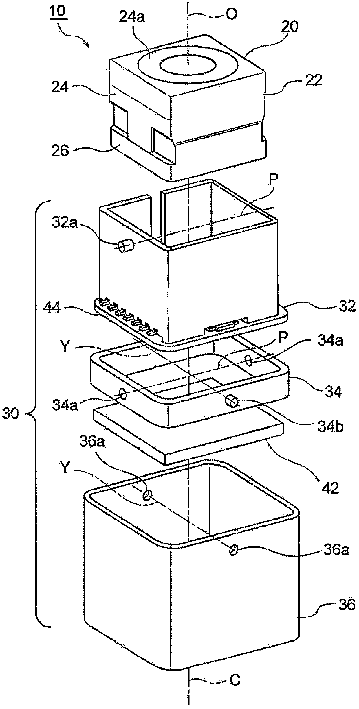
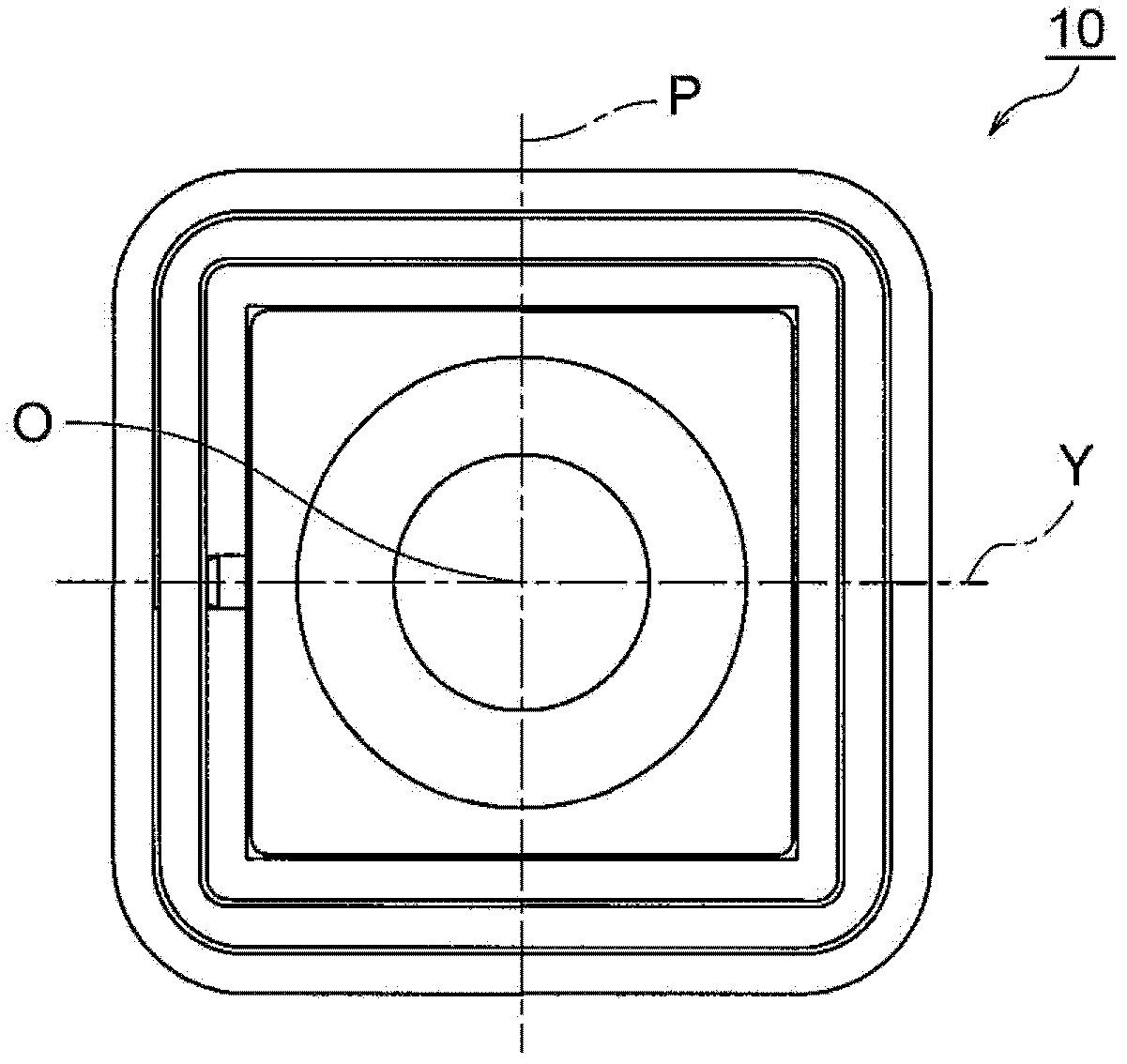
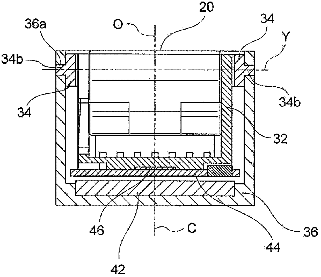
[0051] refer to Figure 1 to Figure 3 , the camera mechanism 10 including the shake correction device 30 according to the first embodiment of the present invention will be described. figure 1 It is an exploded perspective view showing the camera mechanism 10 . figure 2 yes figure 1 A plan view of camera mechanism 10 is shown. image 3 yes figure 1 A front cross-sectional view of camera mechanism 10 is shown.

[0052] The camera mechanism 10 is composed of a camera module 20 and a shake correction device 30 . The camera module 20 holds a lens and an imaging element which will be described later. The illustrated camera module 20 includes an autofocus lens drive unit.

[0053] The autofocus lens driving unit is composed of a lens movable part and a lens driving part. The lens driving part slidably supports the lens movable part in the direction of the optical axis O, a...


PUM


Abstract

The present invention provides a camera hand-shake correction device having a simple structure drive unit (actuator body). The hand-shake correction device (30) corrects hand-shake by maintaining the lens and the camera module (20) of capturing component orthogonal to the optical axis (O), and carrying out shakings around a first axis (P) and a second axis (Y) that crossly intersect so as to fix hand-shake. The hand-shake correction device (30) includes: an inner frame (32) for internally fixing the camera module (20), a middle frame (34) for freely shaking to support the inner frame (32) from its outside surrounding the first axis (P), and an outer frame (36) for freely shaking to support the middle frame from its outside surrounding the second axis (Y) , and a voice coil motor (40) disposed at the bottom of the inner frame and the outer frame. The voice coil motor (40) drives to shake the inner frame (32) and the outer frame (34) that surrounds the first axis (P) and the second axis (Y), respectively.

Description

[0001] This application is a divisional application of a Chinese patent application with an application date of September 24, 2009, an application number of 200910177610.8, and an invention title of "camera shake correction device". technical field [0002] The present invention relates to a camera shake correction device, and more particularly to a camera shake correction device capable of correcting a shake (vibration) generated when a still image is captured, so as to capture an image without image blur. Background technique [0003] Various shake correction devices (image blur correction devices) have been proposed so far, which can prevent blurring of the image on the imaging plane even if there is a shake (vibration) when shooting a still image, and enable clear shooting. [0004] For example, Japanese Unexamined Patent Application Publication No. 2006-65352 (Patent Document 1) discloses an "image blur correction device", which is composed of a plurality of lens groups ...

Claims


Application Information

Patent Timeline
Patent Type & Authority Applications(China)
IPC IPC(8): G03B5/00H04N5/232
CPCG03B2205/0069
Inventor 菅原正吉森谷昭弘
Owner MITSUMI ELECTRIC CO LTD
Why Eureka
Try Eureka