
Inverter device overvoltage protection method

An inverter and overvoltage technology, which is applied in the direction of protection against overvoltage, emergency protection circuit device, output power conversion device, etc., can solve the problem that the number of times of temporary stop does not reach the predetermined number, and achieve The effect of protection against

Inactive Publication Date: 2012-05-02
FUJI ELECTRIC CO LTD
View PDF1 Cites 18 Cited by
  • Summary
  • Abstract
  • Description
  • Claims
  • Application Information

AI Technical Summary

Problems solved by technology

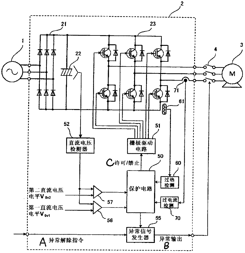
The overvoltage signal is input to the protection circuit 50, and the protection circuit 50 outputs a prohibition signal to the gate drive circuit 51 to temporarily stop the operation of the inverter device 2. However, the number of times of the temporary stop does not reach a predetermined number of times at this time. Therefore, No abnormal output signal is output from the abnormal signal generator 55 to the outside of the inverter device 2

Method used


Image

  • Inverter device overvoltage protection method
  • Inverter device overvoltage protection method
  • Inverter device overvoltage protection method

Examples


Embodiment Construction

[0044] figure 1 It is a block diagram showing the inverter device according to the first embodiment of the present invention, and the parts having the same functions as those of the conventional example are given the same reference numerals, and the description thereof will be omitted.

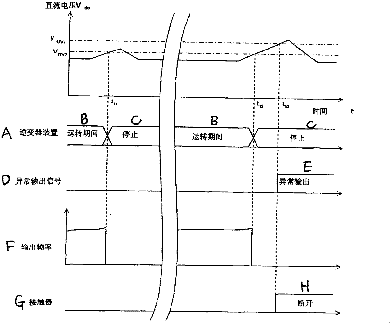
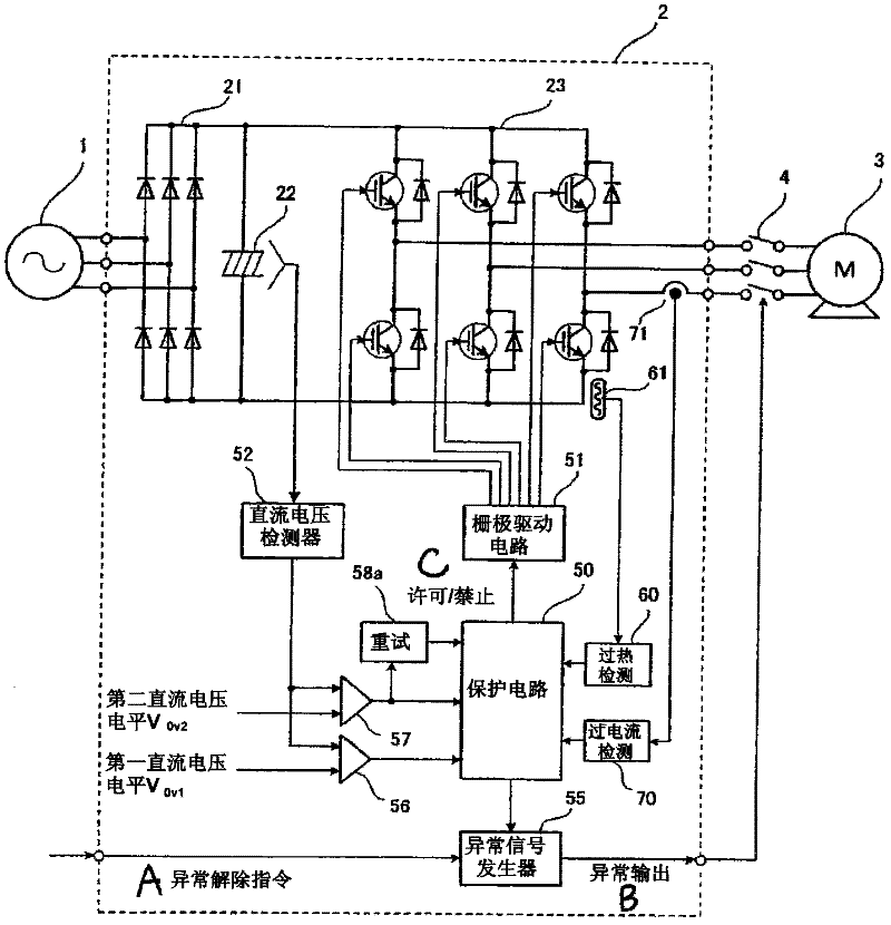
[0045] In the figure, 56 is a first comparator, which detects the DC voltage V detected by the DC voltage detector 52 dc with a predetermined first DC voltage level V 0V1 (Determined as a value of about 130% of the rated DC voltage) for comparison, the DC voltage detection value V dc exceeds the first DC voltage level V 0V1 57 is a second comparator, which detects the DC voltage detection value V detected by the DC voltage detector 52. dc with a predetermined second DC voltage level V 0V2 (Determined as a value of about 125% of the rated DC voltage) for comparison, the DC voltage detection value V dc exceeds the second DC voltage level V 0V2 output overvoltage signal.

[0046] In addit...


PUM


Abstract

An object is to provide an inverter device overvoltage protection method that can appropriately protect the inverter device 2 from an overvoltage condition. When a direct current Voltage rises, and a direct current Voltage detection value detected by a direct current voltage detector 52 exceeds a second direct current voltage level, a protective circuit 50 carries out a stop of the operation of an inverter device 2 by outputting an inhibit signal to a gate drive circuit 51, but it is determined at this time that the rise of the direct current voltage is temporary, and no error output signal is output from an error signal generator 55 to the exterior of the inverter device 2. Meanwhile, in the event that the direct current voltage rises further while the inverter device 2 is temporarily stopped, and the direct current voltage detection value exceeds a first direct current Voltage level, it is determined that protection of the inverter device 2 is necessary, and an error output signal is output to the exterior of the inverter device 2.

Description

technical field [0001] The present invention relates to an overvoltage protection method for an inverter device (inverter device). The inverter device includes: a rectification unit that converts an AC voltage into a DC voltage; The inverter section converts DC voltage to AC voltage. Background technique [0002] When an abnormality such as overvoltage or overcurrent occurs during the operation of the inverter device, a retry operation is performed to automatically restart the operation of the inverter device to continue the operation (for example, Patent Document 1). [0003] Figure 9 A circuit diagram showing a conventional inverter device. [0004] In this figure, 1 is an AC power source such as a commercial power supply, 2 is an inverter device, and 3 is an AC motor. The AC power from the AC power source 1 is converted into AC with variable voltage and variable frequency by the inverter device 2. The converted AC power is used to drive the AC motor 3 at a desired rota...

Claims


Application Information

Patent Timeline
Patent Type & Authority Applications(China)
IPC IPC(8): H02H7/122H02H3/20
CPCH02M7/48H02M5/458H02P29/02H02M1/32H02H7/1222
Inventor 樋口新一
Owner FUJI ELECTRIC CO LTD
Learn More