
Method for manufacturing element for belt of continuously variable transmission

A technology of continuously variable transmission and manufacturing method, which is applied in the direction of household components, applications, belts, etc., can solve the problems of increased manufacturing cost, high manufacturing cost, etc., achieve the effect of smooth flow and save the taper forming process

Inactive Publication Date: 2012-05-02
HONDA MOTOR CO LTD
View PDF8 Cites 5 Cited by
  • Summary
  • Abstract
  • Description
  • Claims
  • Application Information

AI Technical Summary

Problems solved by technology

However, since a special rolling machine is required to form the tapered portions 124, 124, the manufacturing cost is high.
That is, only a single taper forming process will lead to an increase in manufacturing cost

Method used


Image

  • Method for manufacturing element for belt of continuously variable transmission
  • Method for manufacturing element for belt of continuously variable transmission
  • Method for manufacturing element for belt of continuously variable transmission

Examples


Embodiment Construction

[0051] Hereinafter, embodiments of the present invention will be described based on the drawings.

[0052] Embodiments of the present invention will be described based on the drawings.

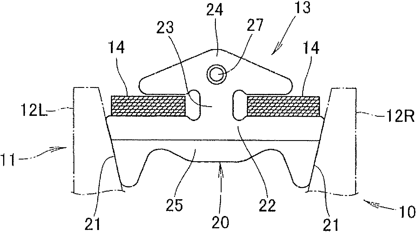
[0053] like figure 1 As shown, a continuously variable transmission (CVT) 10 mainly includes a pair of pulleys 11 (only one is shown) and a belt 13 wound around the pulleys 11 .

[0054] The belt 13 includes: laminated rings 14 , 14 formed by overlapping annular metal rings; and elements 20 supported by the laminated rings 14 , 14 .

[0055] The element 20 includes: a horizontally long main body 22 having left and right sides 21 , 21 abutting on left and right halves 12L, 12R of the pulley 11 ; and a narrow neck extending upward from the main body 22 . 23 ; a triangular-shaped head 24 provided on the upper part of the neck 23 .

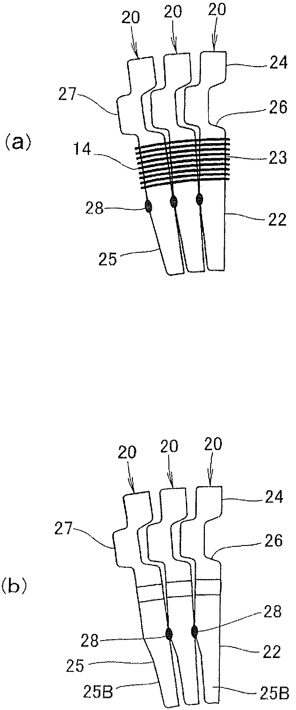
[0056] like figure 2 As shown in (a), the main body portion 22 has a tapered portion 25 tapering downward, and the head portion 24 has a hole 26 and a complemen...


PUM


Abstract

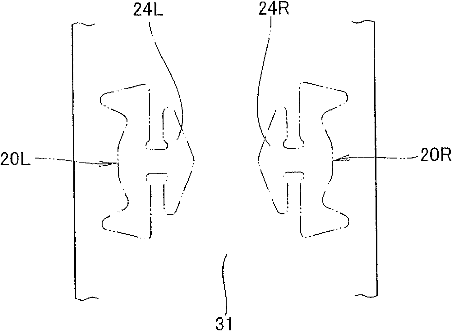
Provided is a method for manufacturing an element for a CVT belt, comprising a body portion (22L, 22R) having right and left sides and a tapered portion with a downwardly reducing width, a neck portion extending upward from the body portion, and a head portion extending upward from the neck portion. The manufacturing method comprises a first punching step in which a metal strip blank (31) which has a uniform thickness and a width which makes it possible to obtain elements arrayed on an even number of lines in an arrangement in which the head portions are opposed to each other or an arrangement in which the body portions are opposed to each other, is punched along an outline (33L, 33R) of an excess material (21b) added to profiles of the left and right sides (21L, 21R) of the body portion, and along an outline (58L, 58R) of an excess material (32b) added to a profile of a lower side (32L, 32R) of the body portion a plastic deformation step in which the blank is compressed in the thickness direction to form a predetermined projection and depression, and form the tapered portion while displacing the material in the outline directions and a second punching step in which the element is obtained as a product by punching the blank.

Description

technical field [0001] The present invention relates to a method of manufacturing an element which is a structural element of a belt built in a continuously variable transmission (CVT). Background technique [0002] CVTs are widely employed in drive systems of vehicles. A metal belt is built into the CVT, and metal parts called elements are included in the metal belt. As prior art related to elements, there are those disclosed in Patent Documents 1 and 2. [0003] based on Figure 17 , the technique disclosed in Patent Document 1 will be described. [0004] Figure 17 It is a diagram illustrating a conventional manufacturing method of an element for a CVT belt. The coiled material 100 is conveyed as indicated by an arrow 101. During this period, a large U-shaped escape hole 102 is first punched out, and then a plurality of concave portions 103, 104 are formed. , 105. Finally, an element 110 is punched out from the roll 100 , and the element 110 includes a main body 107 ,...

Claims


Application Information

Patent Timeline
IPC IPC(8): B21D28/00B21D53/14F16G5/16
CPCB21K23/02B21K23/00F16G5/16B21D28/06B21D53/14Y10T29/49995Y10T29/49996
Inventor 大久保成彦三田和之大西真辅中村慎太郎
Owner HONDA MOTOR CO LTD
Learn More