Continuous time-of-flight scatter simulation method and device

A time-of-flight, scattering point technology, applied in image data processing, instrumentation, 2D image generation, etc., can solve problems such as PET image errors, and achieve the effect of improving quality

Inactive Publication Date: 2013-12-25
KONINKLIJKE PHILIPS ELECTRONICS NV
View PDF9 Cites 1 Cited by
  • Summary
  • Abstract
  • Description
  • Claims
  • Application Information

AI Technical Summary

Problems solved by technology

This wrong assumption will lead to errors in the resulting PET images

Method used


Image

  • Continuous time-of-flight scatter simulation method and device
  • Continuous time-of-flight scatter simulation method and device
  • Continuous time-of-flight scatter simulation method and device

Examples


Embodiment Construction

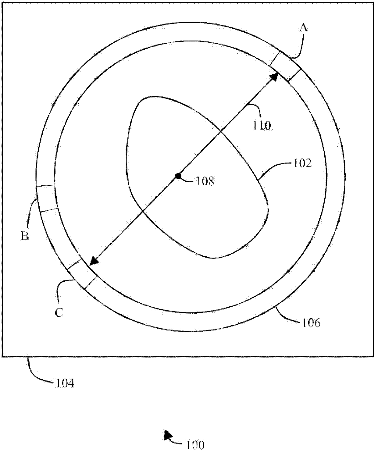
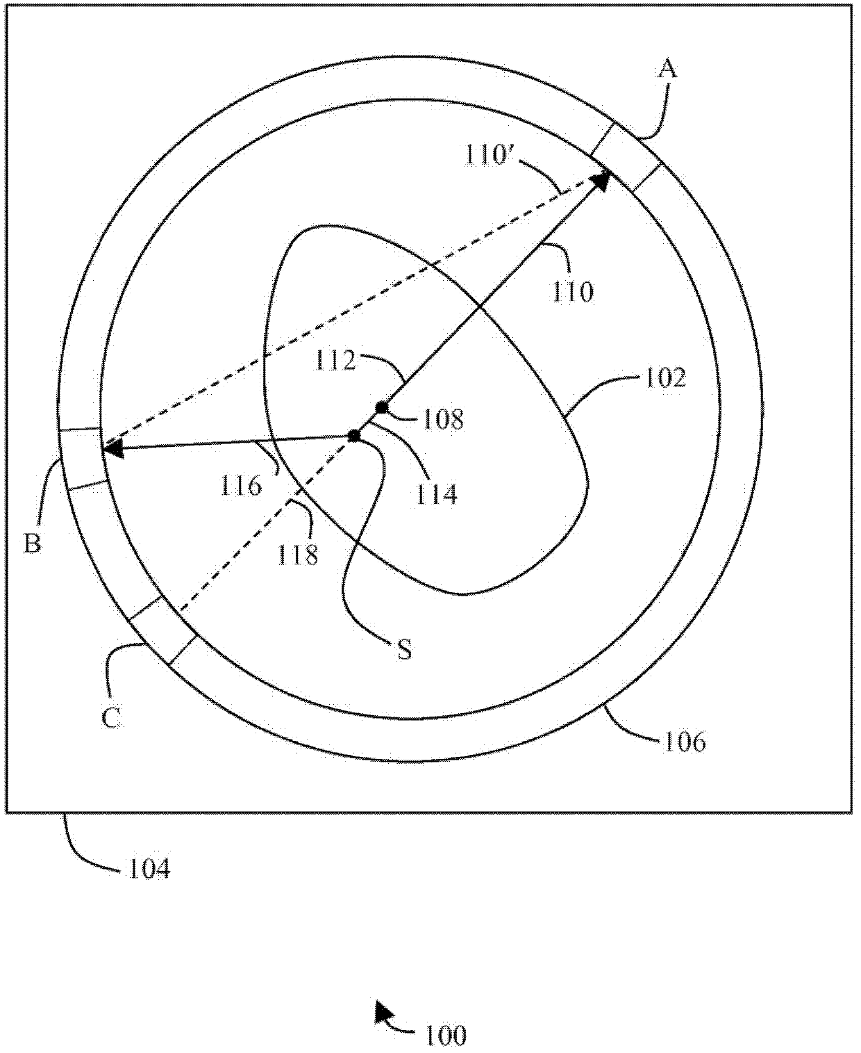
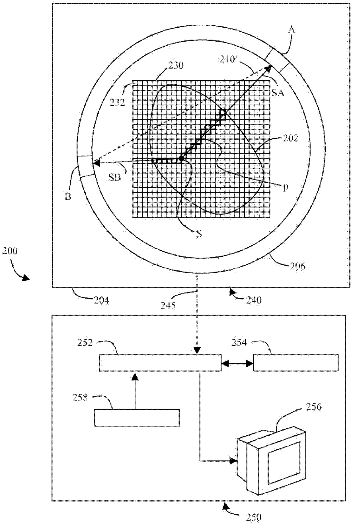
[0016] figure 2 An example of a PET imaging apparatus 200 for performing a PET imaging scan is shown in . The PET imaging acquisition system 240 includes a gantry 204 that houses a patient or other subject 202 to be imaged in a bore. The gantry 204 contains several photon detectors arranged in a ring 206 around the patient 202 to detect coincident photon pairs emitted by positron-electron annihilation. figure 2 Two such detectors A and B are shown in . In an actual PET system 200, the detector ring 206 will typically have several detectors, and typically there will also be many detector rings arranged side by side.

[0017] PET imaging acquisition system 240 communicates PET imaging data recorded by ring 206 of detectors such as A and B to PET imaging, processing and display system 250 via communication link 245 . Although systems 240 and 250 are shown and described herein as separate systems for purposes of illustration, systems 240 and 250 may be part of a single system...


PUM


Abstract

The present invention provides a continuous time-of-flight scattering simulation method and related methods for correcting PET imaging data to compensate for photon scattering. The scatter contribution from each imaging pixel in the field of view can be calculated without binning data.

Description

technical field [0001] The present application relates generally to the field of imaging, and in particular to photon scatter correction in time-of-flight positron emission tomography (PET) scanners. The present application provides a continuous time-of-flight scatter simulation method and an associated method of correcting PET imaging data to compensate for photon scatter. Thus, the present application applies to single modality PET scanners as well as dual modality PET scanners like PET / CT systems and PET / MR systems. Background technique [0002] PET produces images or pictures of internal functional processes, usually in human or animal subjects. To obtain a PET image of a patient, a radiopharmaceutical is first injected into the patient. The radiopharmaceutical comprises a tracer that binds itself to an active molecule of interest, such as glucose, in the patient's body. Radiopharmaceuticals also emit positrons. As the emitted positrons collide with electrons from ne...

Claims


Application Information

Patent Timeline
Patent Type & Authority Patents(China)
IPC IPC(8): G06T1/00G06T11/00
CPCG06T11/005G06T1/00
Inventor P·奥利维尔P·库尔德
Owner KONINKLIJKE PHILIPS ELECTRONICS NV
Why Eureka
Try Eureka