
Brake system for a vehicle and method for operating a brake system for a vehicle

A brake system and automobile technology, applied in the direction of hydraulic brake transmission device, brake action activation device, brake, etc., can solve the problems of expensive and troublesome brake system

Active Publication Date: 2012-05-09
ROBERT BOSCH GMBH
View PDF7 Cites 18 Cited by
  • Summary
  • Abstract
  • Description
  • Claims
  • Application Information

AI Technical Summary

Problems solved by technology

But due to its cumbersome electronics, mechanics and hydraulics, the brake-by-wire braking system is relatively expensive

Method used


Image

  • Brake system for a vehicle and method for operating a brake system for a vehicle
  • Brake system for a vehicle and method for operating a brake system for a vehicle
  • Brake system for a vehicle and method for operating a brake system for a vehicle

Examples


Embodiment Construction

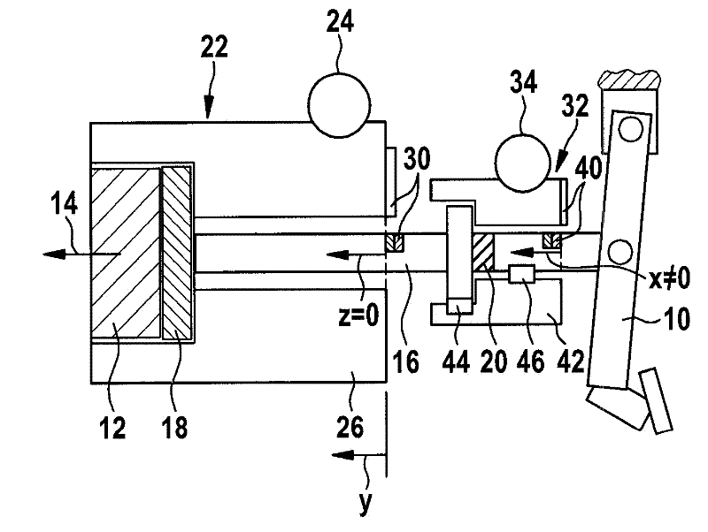
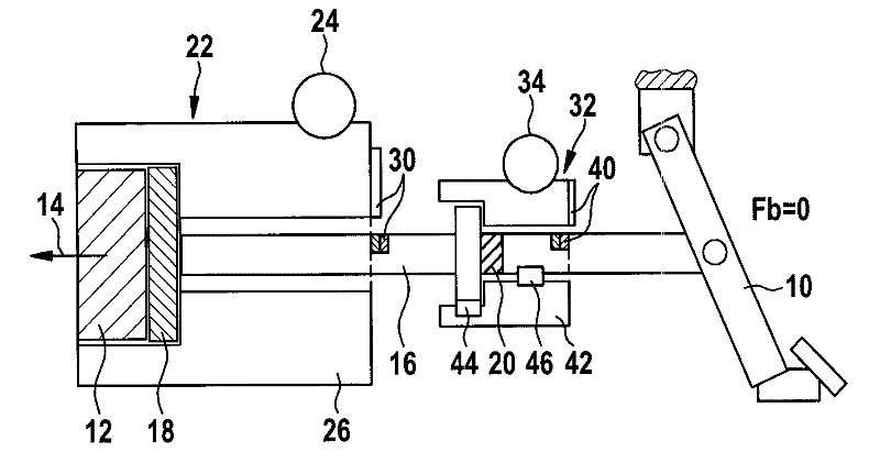
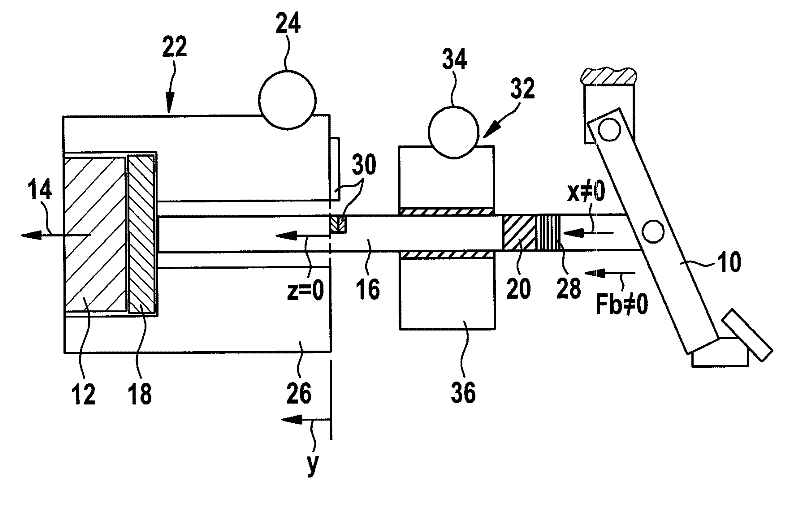
[0016] Figures 1A to 1D A first exemplary embodiment of the brake system is shown schematically in different operating modes.

[0017] exist Figures 1A to 1D The brake system shown only partially in FIG. 2 has a brake actuating element 10 which is formed by a brake pedal. However, the brake system described here is not limited to the formation of brake actuating element 10 by a brake pedal. Alternatively or in addition to the brake pedal, the brake system can also have, for example, a brake actuating element 10 designed for manual actuation.

[0018] For the thus formed vehicle brake, the brake system includes a (not shown) hydraulic brake device having at least one piston-cylinder unit. The output piston 12 is arranged on the piston-cylinder unit in such a way that the internal pressure in the piston-cylinder unit can be increased by adjusting the output piston 12 in the adjustment direction 14 . For this purpose, for example, the output piston 12 can be adjusted at least...


PUM


Abstract

A brake system for a vehicle and a method for operating a brake system for a vehicle are disclosed.The brake system for the vehicle includes: a brake activation element; an input piston displaceable by at least a predefined minimum actuator travel distance when the brake activation element is operated; an output piston to which a driver braking force is transmittable from the brake activation element via the displaced input piston such that an internal pressure in a piston-cylinder unit of the brake system is increased; a first brake booster; and a spring device which, when the brake activation element is operated for an actuator travel distance which is less than the minimum actuator travel distance, is deformed in such a way that transmission of the driver braking force to the output piston is prevented. On the actuation of the brake actuating element (10) by the actuating travel (x) below the minimum actuating travel, the output piston is displaced by means of the first brake booster 22 and as a result the internal pressure in the piston-cylinder unit being can be increased.

Description

technical field [0001] The invention relates to a braking system for a motor vehicle. The invention also relates to a method for operating a braking system of a motor vehicle. Background technique [0002] Electric and hybrid vehicles have braking systems designed for regenerative braking, with electric motors that operate as generators during regenerative braking. The electrical energy obtained during regenerative braking is preferably used for vehicle acceleration after intermediate storage. In this way, the power loss, energy consumption and pollutant emissions of electric or hybrid vehicles are reduced when conventional vehicles brake frequently during driving. [0003] However, a prerequisite for the generator operation of an electric motor, for example an electric drive motor, is usually a certain minimum vehicle speed. Therefore, the regenerative braking system often does not apply a generator braking torque to the vehicle wheels for such a long time until the driv...

Claims


Application Information

Patent Timeline
Patent Type & Authority Applications(China)
IPC IPC(8): B60T7/04B60T11/18
CPCB60T13/588B60T11/18B60T13/745B60T7/042B60T13/586
Inventor R. 魏贝尔勒T. 扬茨
Owner ROBERT BOSCH GMBH
Learn More