
Rotor for centrifugal fluid machine

A fluid mechanical and centrifugal technology, applied in mechanical equipment, liquid fuel engines, components of pumping devices for elastic fluids, etc., can solve the problems of longer processing time, difficult machining, and difficult machining, etc. Achieve the effect of simple structure, firmness, disassembly and assembly, and low-cost production in a short time

Active Publication Date: 2015-05-06
KOBE STEEL LTD
View PDF7 Cites 0 Cited by
  • Summary
  • Abstract
  • Description
  • Claims
  • Application Information

AI Technical Summary

Problems solved by technology

[0008] However, although this conventional rotor can firmly fix the turbine to the rotating shaft (journal), the inner surface shape of the hub forming the through hole of the turbine and the outer surface shape of the rotating shaft fitted therewith have polygonal and conical shapes. For complex shapes such as shapes, it is not easy to perform machining based on cutting, etc., and the processing time becomes longer, and there is a problem that it cannot meet the requirements of high precision and short construction period.
[0009] In particular, with the development of high-speed rotation speed of the turbine, as the material of the turbine, from the conventional carbon steel as the main material to the use of stainless steel and titanium alloys with high corrosion resistance and strength, these new Although the cutting resistance of the material is shown to be low, the machinability is inferior to that of carbon steel. For such difficult-to-cut materials, it is more difficult to machine the above-mentioned turbines with complex shapes in the past with high precision and efficiency, resulting in the following Defects: Special and expensive machine tools that require advanced processing technology and high-precision NC processing equipment

Method used


Image

  • Rotor for centrifugal fluid machine
  • Rotor for centrifugal fluid machine
  • Rotor for centrifugal fluid machine

Examples


Embodiment Construction

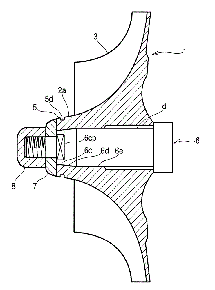
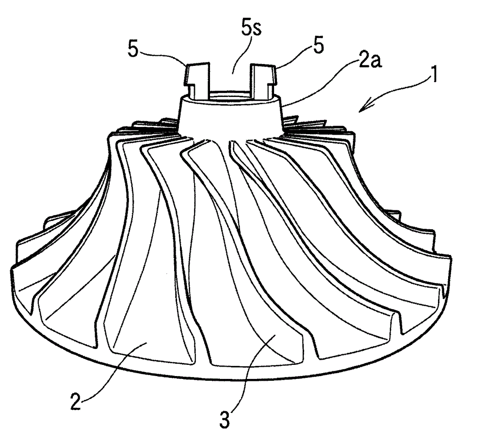
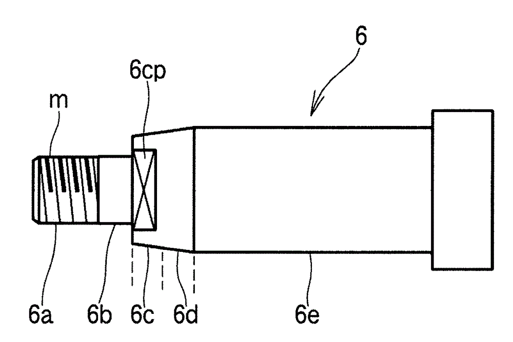
[0024] Hereinafter, typical embodiments in which the present invention is applied to a rotor for a centrifugal compressor (hereinafter, may be simply referred to as the rotor of the present invention) will be described with reference to the drawings. Figure 1 ~ Figure 4 Represents the composition of the turbine of the rotor of the present invention, figure 1 It is a perspective view of the overall appearance of the turbine viewed from the side and above, figure 2 is a partially enlarged perspective view showing the tip portion (gas suction side) of the turbine, image 3 is a partially enlarged plan view showing the tip portion (gas suction side) of the turbine, and Figure 4 is a longitudinal sectional view of the turbine.

[0025] In these figures, the turbine 1 includes a generally conical hub 2 and a plurality of (18 in this example) vanes (blades) 3 spirally arranged on the outer peripheral surface of the hub, as is well known. The impeller is rotated at a high speed ...


PUM


Abstract

PROBLEM TO BE SOLVED: To provide a rotor for centrifugal fluid machinery which does not require complex and difficult processing for an impeller and the like, which can firmly fix the impeller to a rotary shaft with a simple configuration, and in which the impeller can be simply removed from and attached to the rotary shaft. SOLUTION: The rotor for centrifugal fluid machinery includes: a pair of projections 5 on an end part 2a of a hub of the impeller 1, which face each other and whose both side faces are plane; a male screw part having a screw groove formed on an outer circumference, on an end of the rotary shaft 6; a plane part 6c whose both sides are plane, on a root side from the male screw part; a lock ring 7 which has a through-hole in a center part, includes two planes facing each other, and a groove part accommodating the projections 5 of the hub of the impeller 1 and the plane part 6c of the rotary shaft 6; and a lock nut 8 which has a female screw part formed in a center part, and in which the female screw part and the male screw part 6a of the rotary shaft 6 are screwed.

Description

technical field [0001] The present invention relates to a rotor for a centrifugal fluid machine such as a centrifugal compressor that rotates a turbine (impeller) at high speed to compress or expand a fluid, or a centrifugal expander. Background technique [0002] As is well known, generally in a centrifugal compressor or a centrifugal expander, the rotor is formed by inserting and detachably fixing a turbine composed of a hub on the rotating shaft. combined through-holes, and a plurality of fins (blades) are provided on its outer periphery. [0003] Since the turbine rotates at high speed, it is required to fix the turbine to the rotating shaft very firmly. On the other hand, there is also a demand for a configuration capable of facilitating attachment and detachment of the turbine from the rotating shaft in accordance with maintenance at predetermined intervals. Therefore, in the rotors of these centrifugal fluid machines, various proposals have been made on how to fix t...

Claims


Application Information

Patent Timeline
Patent Type & Authority Patents(China)
IPC IPC(8): F04D29/28F04D29/04F01D5/02
Inventor 梶木一俊
Owner KOBE STEEL LTD
Learn More