Navigation device
A technology of navigation device and installation location, applied in navigation, measuring device, surveying and mapping and navigation, etc., can solve the problems of narrow side of disassembly and assembly unit, smaller display area, and not necessarily visual recognition, so as to increase the size and improve disassembly and assembly. The effect of freedom
- Summary
- Abstract
- Description
- Claims
- Application Information
AI Technical Summary
Problems solved by technology
Method used
Image
Examples
Embodiment 1
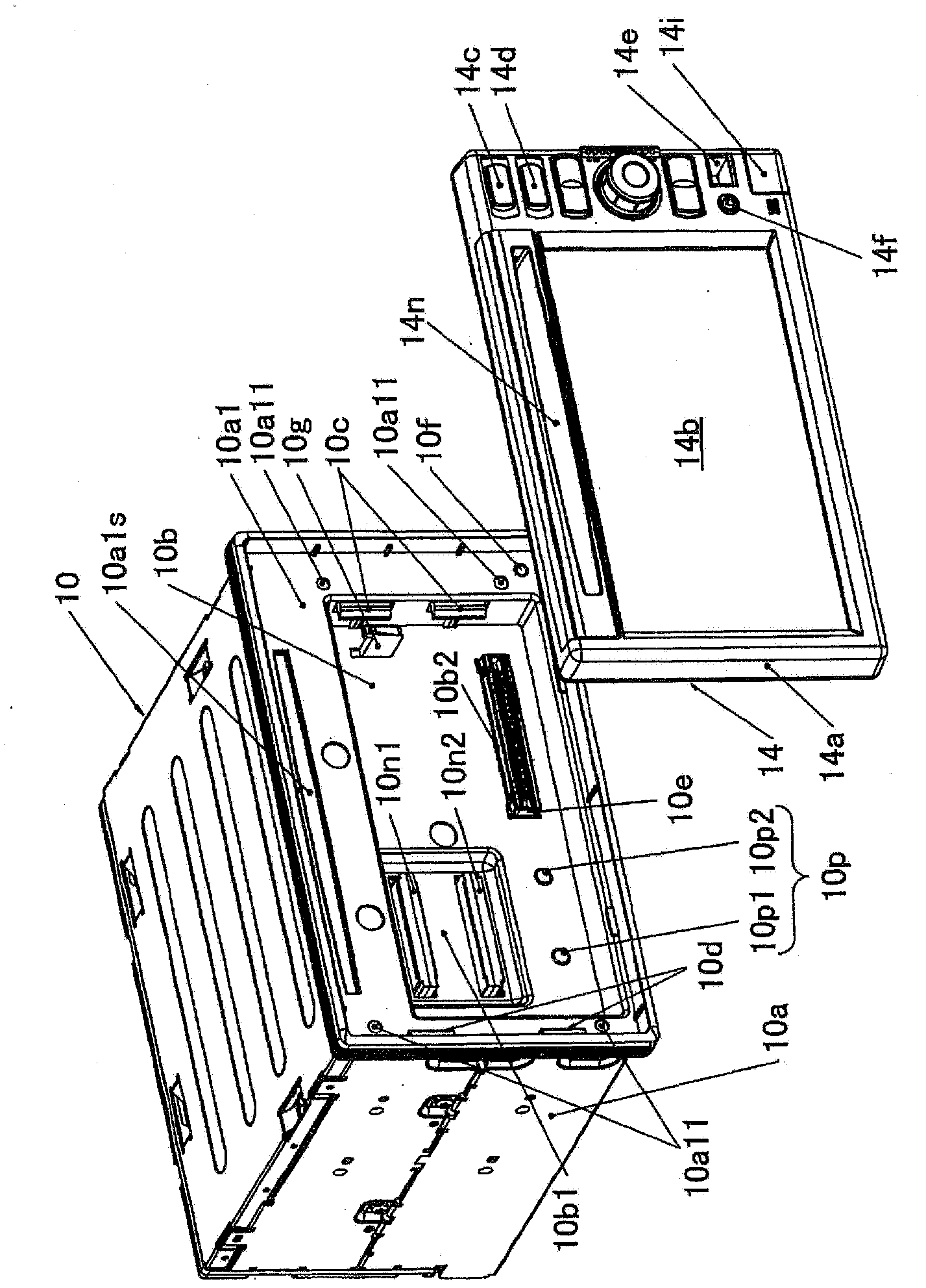
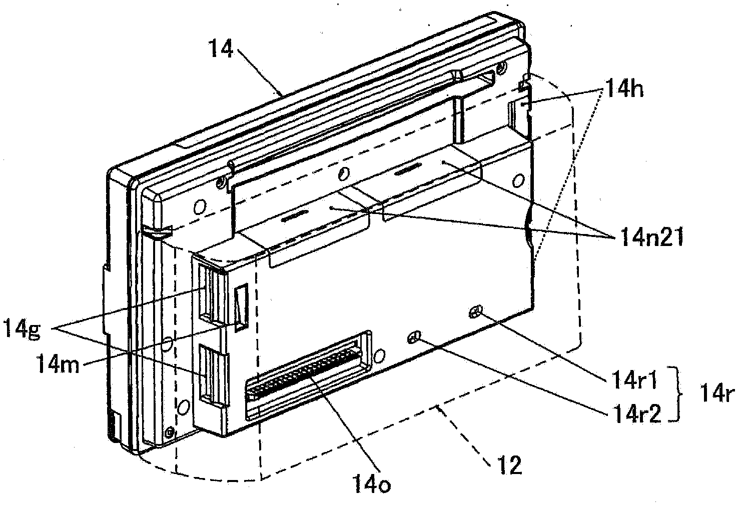
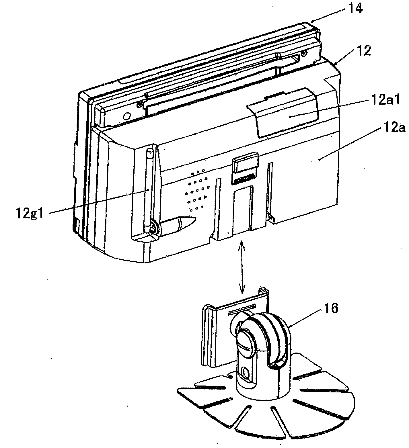
[0082] figure 1 It is a perspective view of the front side of the base unit and the front panel unit in the navigation device of the first embodiment of the present invention, figure 2 is a perspective view of the rear side of the front panel unit, image 3 It is a perspective view of the front panel unit (rear side), the bracket unit, and the bracket unit mounting arm. Figure 4 is an explanatory diagram showing a state in which it is mounted on a vehicle, Figure 5 (a) is an explanatory drawing of the driver's seat of the vehicle, Figure 5 (b) Its side view near the steering wheel. Figure 6 and Figure 7 is a cross-sectional view of the base unit 10 and the front panel unit 14 viewed from above, Figure 8 and Figure 9 is a partial cross-sectional view of the base unit 10 and the front panel unit 14 viewed from the right side, Figure 10 (a), (b), and (c) are explanatory diagrams of the front panel unit 14 .
[0083] As shown in the figure, the navigation device a...
Embodiment 2
[0207] Figure 31 is a perspective view showing a state in which a navigation device according to a second embodiment of the present invention is mounted on a vehicle, Figure 32 From Figure 31 A front view of a state where the front panel unit 14 is removed, Figure 33 for Figure 32 Illustrative cross-sectional view of .
[0208] with Figure 5 and Figure 11 The different points of the first embodiment shown by etc. are focused on the description, and in the second embodiment, such a structure is adopted: as Figure 32 As shown, the base unit 10 is housed in such a manner that it is completely built into the inside of the rectangular recess 24 formed on the instrument panel D, and when the front panel unit 14 is installed, as shown in FIG. Figure 31 As shown, the upper portion of the front panel unit 14 , more specifically, the front panel unit case 14 a protrudes from the wall surface Dw of the instrument panel D. As shown in FIG.
[0209] That is, the base unit 1...
Embodiment 3
[0223] Figure 34 is a perspective view showing a state in which a navigation device according to a third embodiment of the present invention is mounted on a vehicle, Figure 35 is a front view when the front panel unit 14 is removed from this state, Figure 36 and Figure 37 It is also a perspective view shown in a state mounted on a vehicle, Figure 38 yes means Figure 34 An explanatory diagram of the relationship between the front panel unit 14 , the base unit 10 , the instrument panel D, and an upper cover described later shown in FIG.
[0224] Focusing on the differences from the previous embodiments, in the third embodiment, in Figure 34In the side view shown, formed on the gently sloping dashboard D Figure 35 The inside of the housing portion 38 shown accommodates the base unit 10 , and the base unit 10 , more specifically, the vicinity of the opening of the base unit case 10 a is surrounded by a decorative panel 40 .
[0225] The opening end of the decorative ...
PUM
 Abstract
Description
Claims
Application Information
 - R&D
- Intellectual Property
- Life Sciences
- Materials
- Tech Scout
- Unparalleled Data Quality
- Higher Quality Content
- 60% Fewer Hallucinations
Browse by: Latest US Patents, China's latest patents, Technical Efficacy Thesaurus, Application Domain, Technology Topic, Popular Technical Reports.
© 2025 PatSnap. All rights reserved.Legal|Privacy policy|Modern Slavery Act Transparency Statement|Sitemap|About US| Contact US: help@patsnap.com


