
Clamping device for linear displacement sensor

The technology of a linear displacement sensor and a clamping device, which is applied in the field of machining, can solve the problems of adjusting the direction of the pull rod, affecting the calibration measurement accuracy and work efficiency, and cumbersome adjustment of the sensor direction, so as to achieve the effect of improving work efficiency and reducing costs.

Active Publication Date: 2012-05-09
XIAN AIRCRAFT DESIGN INST OF AVIATION IND OF CHINA
View PDF5 Cites 12 Cited by
  • Summary
  • Abstract
  • Description
  • Claims
  • Application Information

AI Technical Summary

Problems solved by technology

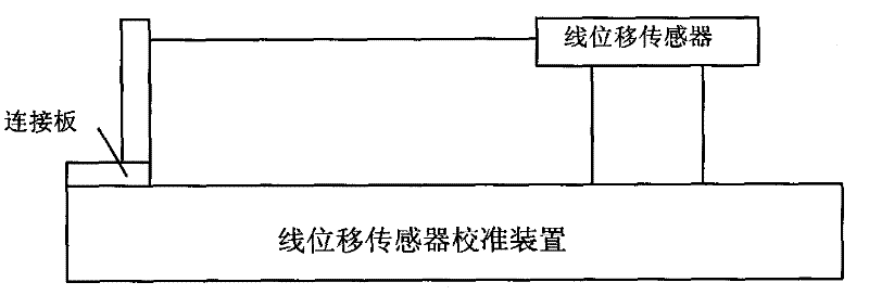
[0002] In the process of calibrating the linear displacement sensor, there is only one fixed connection plate on the calibration device of the linear displacement sensor, which cannot adjust the direction of the pull rod of the linear displacement sensor. Different connection plates are used to clamp the linear displacement sensor, and the adjustment of the direction of the sensor is also very cumbersome. It is necessary to lock the screw for a while, and then loosen it for a while. It is not easy to adjust to the ideal state, which affects the measurement accuracy of calibration and work efficiency

Method used


Image

  • Clamping device for linear displacement sensor
  • Clamping device for linear displacement sensor
  • Clamping device for linear displacement sensor

Examples


Embodiment Construction

[0015] The present invention will be further described below by means of specific embodiments:

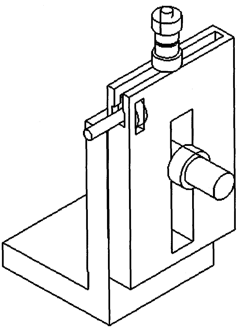
[0016] A clamping device for a linear displacement sensor, characterized in that it includes an alloy plate 1, an adjusting nut 2, a spring 3, a slider 4, an adjusting bolt 5, a bolt 6, a lock nut 7, a stud 8, and a tightening nut 9 , the vertical connecting plate 10 of the calibration device, the locking bolt 11, the second locking nut 12,

[0017] A convex groove is opened on the side surface of the alloy plate 1. At one end of the convex groove, there is an adjusting nut groove perpendicular to the convex groove. The adjusting nut 2 is embedded in the adjusting nut groove. One end is embedded in the spring 3 and the slider 4 in turn, and the adjusting bolt 5 is in contact with the slider 4 through the adjusting nut 2;

[0018] Slide block 4 is fixed with a bolt 6 in the vertical direction, and bolt 6 passes through the convex-shaped groove and is fastened by the lock nut 7 on t...


PUM


Abstract

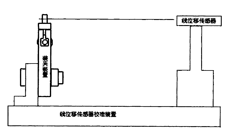
The invention discloses a clamping device for a linear displacement sensor, which belongs to the technical field of machining and specifically relates to an improvement on the clamping device of the linear displacement sensor. The clamping device consists of a fixing support, an actuating barrel, a rocking arm connecting rod mechanism, a side rolling shaft, a side rolling shaft sleeve, a side rolling fork lug and an oil filling pipe connecting support, wherein the side rolling shaft sleeve consists of a front end cover, a barrel body and a back end cover; the connecting relations of the assemblies are that: the fixing support is connected with the actuating barrel, a rocking arm and the side rolling shaft sleeve in hinging way; the actuating barrel is connected with the rocking arm in a hinging way; the connecting rod is connected with the side rolling shaft sleeve in a hinging way; the side rolling shaft is supported by a bearing and a bush in the side rolling shaft sleeve; the side rolling shaft passes through the back end cover of the side rolling shaft sleeve, and is tightened with the side rolling fork lug through a bolt; and the slide rolling fork lug is connected with the oil filling pipe connecting support in a hinging way. Due to the adoption of the clamping device, the measuring and testing accuracies are increased, the cost is reduced simultaneously, and the working efficiency is increased.

Description

technical field [0001] The invention belongs to the technical field of mechanical processing, and in particular relates to an improvement of a clamping device of a linear displacement sensor. Background technique [0002] In the process of calibrating the linear displacement sensor, there is only one fixed connection plate on the calibration device of the linear displacement sensor, which cannot adjust the direction of the pull rod of the linear displacement sensor. Different connection plates are used to clamp the linear displacement sensor, and the adjustment of the direction of the sensor is also very cumbersome. It is necessary to lock the screw for a while, and then loosen it for a while. It is not easy to adjust to the ideal state, which affects the measurement accuracy of calibration and work efficiency. Through working experience, the invention of this set of pull wire type displacement sensor clamping fixture is not only simple but also applicable. It is very conv...

Claims


Application Information

Patent Timeline
Patent Type & Authority Applications(China)
IPC IPC(8): G01B21/02
Inventor 段新文曹春
Owner XIAN AIRCRAFT DESIGN INST OF AVIATION IND OF CHINA
Learn More