
Permanent magnet and low-frequency rotating constant-strength magnetic field treatment device employing the same

A treatment device and permanent magnet technology, applied in the direction of variable magnetic field generated by mechanical movement, permanent magnet, inductance/transformer/magnet manufacturing, etc., can solve the problem of low rise height of magnetic force line, imperfect treatment effect, and inability of magnetic force line to penetrate Treatment of parts and other problems to achieve the effect of reducing operating noise and increasing the lifting height

Inactive Publication Date: 2012-05-09
深圳市恒安鸿源磁科技有限公司
View PDF9 Cites 12 Cited by
  • Summary
  • Abstract
  • Description
  • Claims
  • Application Information

AI Technical Summary

Problems solved by technology

[0003] In summary, the purpose of the present invention is to solve the technical problem that the existing permanent magnet magnetic field line used for magnetic therapy has a low rise height, and the magnetic force line cannot penetrate the treatment site, resulting in an imperfect treatment effect. A permanent magnet and its application are proposed. The permanent magnet low-frequency rotating strong constant magnetic field treatment device

Method used


Image

  • Permanent magnet and low-frequency rotating constant-strength magnetic field treatment device employing the same
  • Permanent magnet and low-frequency rotating constant-strength magnetic field treatment device employing the same
  • Permanent magnet and low-frequency rotating constant-strength magnetic field treatment device employing the same

Examples


Embodiment Construction

[0021] Below in conjunction with accompanying drawing and preferred specific embodiment, structure of the present invention is described further:

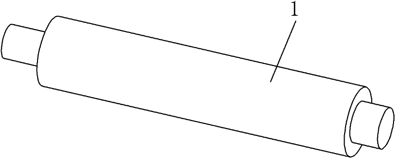
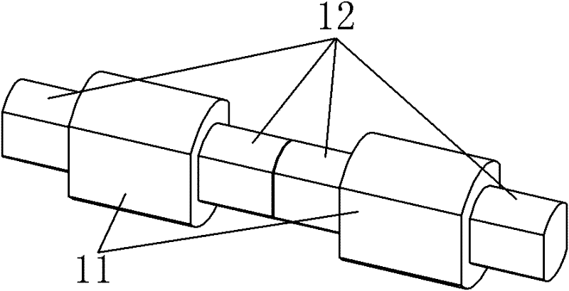
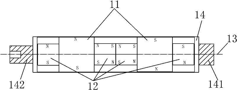
[0022] refer to figure 1 , figure 2 and image 3 As shown in , the permanent magnet 1 of the present invention is composed of at least one active magnet 11 and more than two guiding magnets 12, figure 2 and image 3 Two action magnets 11 and four guide magnets 12 are used as examples in the above, wherein the guide magnets 12 have the same shape as the action magnets 11, but their size is smaller than the size of the action magnets 11, preferably 1 / 2 of the size of the action magnets 11 Between three-quarters, the size of the guide magnet 12 is two-thirds of the size of the action magnet 11, which is the most preferred size. Arrange all the action magnets 11 and guide magnets 12 in a row, wherein each action magnet 11 is provided with a guide magnet 12 on the left and right sides, and the action magnet 11 is placed perpendicu...


PUM


Abstract

A permanent magnet and a low-frequency rotating constant-strength magnetic field treatment device employing the same relate to the technical field of the magnet therapy treatment device and solve the technical problem of imperfect treatment effect because the magnetic lines of force of the magnetic field of the existing permanent magnet for magnet therapy are low in raising height and thereby areincapable of penetrating through a treatment part. The permanent magnet comprises at least one acting magnet and more than two guide magnets, all of which are arranged in one row, wherein the size ofthe guide magnet is smaller than that of the acting magnet; the guide magnets are arranged on the left and right sides of each acting magnet, respectively; and the magnetic poles of the acting magnetand the guide magnets are arranged so that the same magnetic properties are in contact with each other. Besides, the motor shaft of a drive motor is connected to one end of the permanent magnet through a magnetic flexible connection structure. The field of the magnetic field is enhanced; the human body can be prevented from harm caused by accidental contact of the human body with the permanent magnet; the noise of running is reduced; and the burnout of the motor is also avoided after the magnet is hindered to stop rotating.

Description

technical field [0001] The invention relates to the technical field of a magnetic therapy device, in particular to a low-frequency rotating permanent magnet strong magnetic field therapy device. Background technique [0002] Magnetic fields have obvious effects on the human body and other organisms, water or chemical agents. In view of this, magnetic fields are applied to the human body to treat the human body with local strong magnetic fields, commonly known as magnetic therapy. Magnetic therapy is no stranger to modern medicine, and magnetic therapy instruments are not uncommon, such as: Chinese patent (application number: 88213746.4) "electric magnetic therapy machine", Chinese patent (application number: 86206534) "rotating magnetic machine", the United States Patent (Application No. 4,537,131) "Magnetic Device for Eliminating Calcium Deposition in the Human Body by Non-surgical Operations" etc., all have different deficiencies. For the deficiencies of the above-mentione...

Claims


Application Information

Patent Timeline
IPC IPC(8): H01F7/02H01F41/02A61N2/12
Inventor 张功弼
Owner 深圳市恒安鸿源磁科技有限公司
Learn More