
Solar hot air balloon

A technology of solar heating and balloons, which is applied in the direction of balloon aircraft, electrical components, electric vehicles, etc., can solve the problems of propane or liquefied gas explosion, the limitation of hot air balloon endurance, and the short endurance time of hot air balloons, so as to improve the ascent speed and High, good economic benefits, easy to promote the effect of implementation

Pending Publication Date: 2019-08-23
聂武杰
View PDF8 Cites 0 Cited by
  • Summary
  • Abstract
  • Description
  • Claims
  • Application Information

AI Technical Summary

Problems solved by technology

But, present hot-air balloon itself still exists very big restriction and deficiency
To sum up, it can be divided into the following points: First, hot air balloons mostly use propane or liquefied gas as fuel. At present, most of the production of propane comes from the by-products of crude oil and natural gas smelting, and both are non-renewable resources. Renewable raw materials produce propane, so propane will be used less and less. If hot air balloons cannot use new energy instead of propane or liquefied gas, they will be eliminated; secondly, hot air balloon flight has higher requirements on meteorological conditions. When it is larger, the burning of propane or liquefied petroleum gas may burn the hot air balloon, so there are strict requirements on the wind speed in the air when the hot air balloon flies, and the ground wind speed is also higher when the hot air balloon takes off the ball; third, the endurance of the hot air balloon It will be limited by the amount of fuel carried, and the life of a general hot air balloon is relatively short.
Fourth, improper use of propane or liquefied petroleum gas may cause an explosion, causing loss of life and property

Method used


Image

  • Solar hot air balloon
  • Solar hot air balloon
  • Solar hot air balloon

Examples


Embodiment

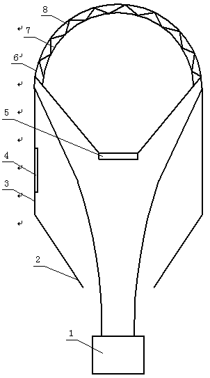
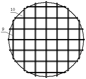
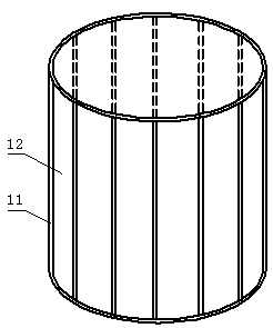
[0025] Example: see Figure 1-Figure 4 , in the figure, 1-hanging basket; 2-lower cone; 3-middle cylinder; 4-access door; 5-controller; 6-upper spherical crown; -spherical crown fixing strip; 10-translucent tarpaulin; 11-cylinder fixing strip; 12-transparent plastic; 13-cone cylinder fixing strip; 14-cone cylinder tarpaulin.

[0026] The solar hot air balloon includes an upper spherical cap 6, a hanging basket 1 and a controller 5, wherein: the upper spherical cap 6 is composed of a spherical cap fixing strip 9 and a light-transmitting tarpaulin 10, and a heat-absorbing ball is arranged in the inner cavity of the upper spherical cap 6 Crown 7, connecting piece 8 is arranged between upper spherical cap 6 and heat-absorbing spherical cap 7, heat-absorbing spherical cap 7 is made of heat-absorbing material, absorbs sunlight to heat the air in heat-absorbing spherical cap 7, and upper spherical cap 6 is connected to the upper end of the middle cylinder 3 through a hanging piece, ...


PUM


Abstract

The invention discloses a solar hot air balloon which comprises an upper spherical crown, a hanging basket and a controller. The upper spherical crown is composed of a spherical crown fixing strip andlight-transmitting tarpaulin, a heat absorbing spherical crown is arranged in an inner cavity of the upper spherical crown, a connecting member is arranged between the upper spherical crown and the heat absorbing spherical crown, and the heat absorbing spherical crown is made of a heat absorbing material and absorbs sunlight to heat air in the heat absorbing spherical crown. The upper spherical crown is connected to the upper end of a middle cylinder through a hanging member, the middle cylinder is composed of a cylinder fixing strip and transparent plastic, the lower end of the middle cylinder is connected to the upper end of a lower cone through a hanging member, the lower cone is composed of a cone fixing strip and cone tarpaulin, the lower end of the lower cone is provided with an opening, and the hanging basket can be dropped from the opening. The solar hot air balloon utilizes solar energy to heat the air in the spherical crown, so that the air expands, the density becomes smaller, the hot air balloon is accordingly driven to rise, no other power is needed, and energy consumption is saved.

Description

[0001] Technical field: [0002] The invention relates to a hot air balloon, in particular to a solar hot air balloon. [0003] Background technique: [0004] A hot air balloon is a balloon that uses hot air as the buoyant gas, and consists of three parts: a balloon, a hanging basket and a heating device. Modern hot air balloons are equipped with simple flight instruments, fuel tanks and blowtorches in the gondola. When launching from the ground, the blowtorch is lit, and the heated air is inflated into the balloon through the opening at the bottom of the balloon. After flying into the air, control the fuel injection quantity of the blowtorch to control the ascent or descent of the balloon. Hot air balloons appeared first, and now flying in hot air balloons has become a favorite aviation sport. [0005] In addition, hot air balloons are also commonly used in aerial photography and air travel. But present hot-air balloon itself also has very big limitation and deficiency. T...

Claims


Application Information

Patent Timeline
Patent Type & Authority Applications(China)
IPC IPC(8): B64B1/40H02J7/35
CPCB64B1/40H02J7/35
Inventor 聂武杰赵明成
Owner 聂武杰
Learn More