Gas breaker

A gas circuit breaker and gas technology, applied in the direction of high-voltage air circuit breakers, circuits, electrical components, etc., can solve the problems of reducing gas diversion, poor arc suppression performance, danger, etc., and achieve the goal of reducing fluid resistance and improving arc suppression performance Effect

Active Publication Date: 2012-05-09
HITACHI LTD
View PDF4 Cites 5 Cited by
  • Summary
  • Abstract
  • Description
  • Claims
  • Application Information

AI Technical Summary

Problems solved by technology

Therefore, in the conventional example, there is a problem that the circulation effect is weak and the arc extinguishing performance is also poor.
[0013] In addition, when the medium and small currents are cut off, there is a risk that the gas flowing from th

Method used


Image

  • Gas breaker
  • Gas breaker
  • Gas breaker

Examples


Embodiment 1)

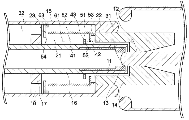
[0034] In the circuit breaker of the gas circuit breaker of the embodiment of the present invention, such as figure 1 As shown, the thermal blast chamber 21 and the variable-volume mechanical blast chamber 32 are provided in series via the partition wall 17 forming the communicating portion 18 of the opening. Inside the heat injection chamber 21 , a cylindrical partition member 41 is provided which divides the inside in the radial direction and divides it into an inner peripheral side space 61 and an outer peripheral side space 62 .

[0035] In addition, the communication part 18 constituting the opening part formed in the partition wall 17 is figure 1 In the example shown, it is installed on the side of the cylinder 15, but it may be installed at a position that does not hinder the inflow of arc-extinguishing gas that flows from the side of the mechanical injection chamber 32 as will be described later.

[0036] This partition member 41 includes, for example, the following...

Embodiment 2)

[0068] Figure 6 Another embodiment of the gas circuit breaker of the present invention is shown. In this embodiment, with respect to the above-mentioned embodiment 1, when the movable valve 23 is in an open state, the end face of the movable valve 23 and the partition member 41 on the side of the mechanical jet chamber 21 is in close contact, thus, the outer peripheral side space of the heat jet chamber 21 62 is disconnected from the inner peripheral space 61 .

[0069] When the medium and small currents are cut off, the rising degree of the pressure of the heat jet chamber 21 is less large when the large current is cut off, so the pressures of the mechanical jet chamber 32 and the heat jet chamber 21 are balanced. Accordingly, the movable valve 23 does not close the communicating portion 18 .

[0070] Near the zero point of the current, the mechanical jet chamber 32 is compressed by the breaking action. As a result, the pressure in the mechanical jet chamber 32 rises, and...

Embodiment 3)

[0074] Figure 7 Another example of the gas interrupter of the present invention is shown. In this embodiment, a polymer material 71 such as tetrafluoroethylene resin having an ablation effect is provided in the outer peripheral space 62 in the heat injection chamber 21 partitioned by the partition member 41 as compared to the above-mentioned embodiment 1.

[0075] If formed in this way, the high-temperature arc-extinguishing gas flowing from the arc space 31 into the thermal arc chamber 21 can directly contact the polymer material, effectively increasing the pressure, and obtaining higher breaking performance.


PUM


Abstract

For forming a gas breaker which effectively realizes large electric current switching-off and medium/small electric current switching-off, a heat gas jetting chamber (21) and a mechanical gas jetting chamber (32) are equipped in series. In the heat gas jetting chamber (21), a spacing component (41) is equipped. The spacing component divides the inner part of the chamber along a radial direction for dividing to an inner periphery side space (61) and an outer periphery side space (62). A switching valve (42) which is used as a gas flow control mechanism is equipped between an arc space (31) and the heat gas jetting chamber (21). A movable valve (23) is equipped for opening and closing a communication part (18) of a spacing wall (17) between the heat gas jetting chamber (21) and the mechanical gas jetting chamber (32). When the large electric current is switched off, high-temperature and high-pressure de-arcing gas which comes from the arc space (31) is blown to the arc by means of the switching valve (42) from the outer periphery side space (62) of the spacing component (41) through the inner periphery side space (61). When the medium-small current is switched off, the de-arcing gas which comes from the mechanical gas jetting chamber (32) is only guided to the inner periphery side space (61) of the spacing component and is blown to the electric arc.

Description

technical field [0001] The present invention relates to a jet type gas circuit breaker, and particularly relates to a jet type gas circuit breaker utilizing mechanical compression and heating and boosting action of arc heat. Background technique [0002] The heat jet gas circuit breaker with both heat jet chambers and mechanical jet chambers is suitable for breaking large currents and is used in high voltage systems. On the contrary, there is a problem that it is difficult to cut off medium and small currents. Therefore, in recent years, people have attempted to use jet-type gas circuit breakers to cut off not only large currents, but also medium and small currents. [0003] For example, JP Unexamined Patent Publication No. 2009-99499 (Patent Document 1) discloses a gas circuit breaker for the purpose of interrupting a current from a small current to a large current. Figure 8 The gas circuit breaker described in this patent document 1 (hereinafter referred to as a conventi...

Claims


Application Information

Patent Timeline
IPC IPC(8): H01H33/91
CPCH01H33/08H01H33/7023H01H33/74H01H33/82H01H33/91
Inventor 作山俊昭浦井一大下陽一小泉眞柳沼宣幸佐藤賢廣瀬誠
Owner HITACHI LTD
Why Eureka
Try Eureka