
Gas insulation switch

A gas-insulated switch and insulating gas technology, applied in the direction of electric switches, high-voltage/high-current switches, electrical components, etc., can solve the problems of reduced electric field characteristics, easy melting, damage to the same components, etc., to reduce the number of components, high insulation The effect of stable voltage resistance and insulation performance

Active Publication Date: 2010-09-29
JAPAN AE POWER SYST
View PDF12 Cites 0 Cited by
  • Summary
  • Abstract
  • Description
  • Claims
  • Application Information

AI Technical Summary

Problems solved by technology

[0003] However, in the conventional gas insulated switch, in terms of the device provided with the gas blowing mechanism to improve the breaking performance of the loop current, not only the main energization contact or the elastic contact member or the protective shield located near the arc generating part The cover is easily melted by heat, and there is a possibility that the conduction performance or insulation performance may be reduced due to the ignition of the arc at the same part located on the downstream side of the blown air flow, or contact with high-temperature metal vapor
In addition, even when an arc contact is provided, the potential of the arc contact is different from that of nearby components due to resistance. Therefore, if the insulation distance is ensured, the electric field characteristics will be reduced, and the same components arranged nearby may be damaged. Danger

Method used


Image

  • Gas insulation switch
  • Gas insulation switch
  • Gas insulation switch

Examples


Embodiment Construction

[0037] Hereinafter, the best mode for carrying out the present invention will be described with reference to the drawings.

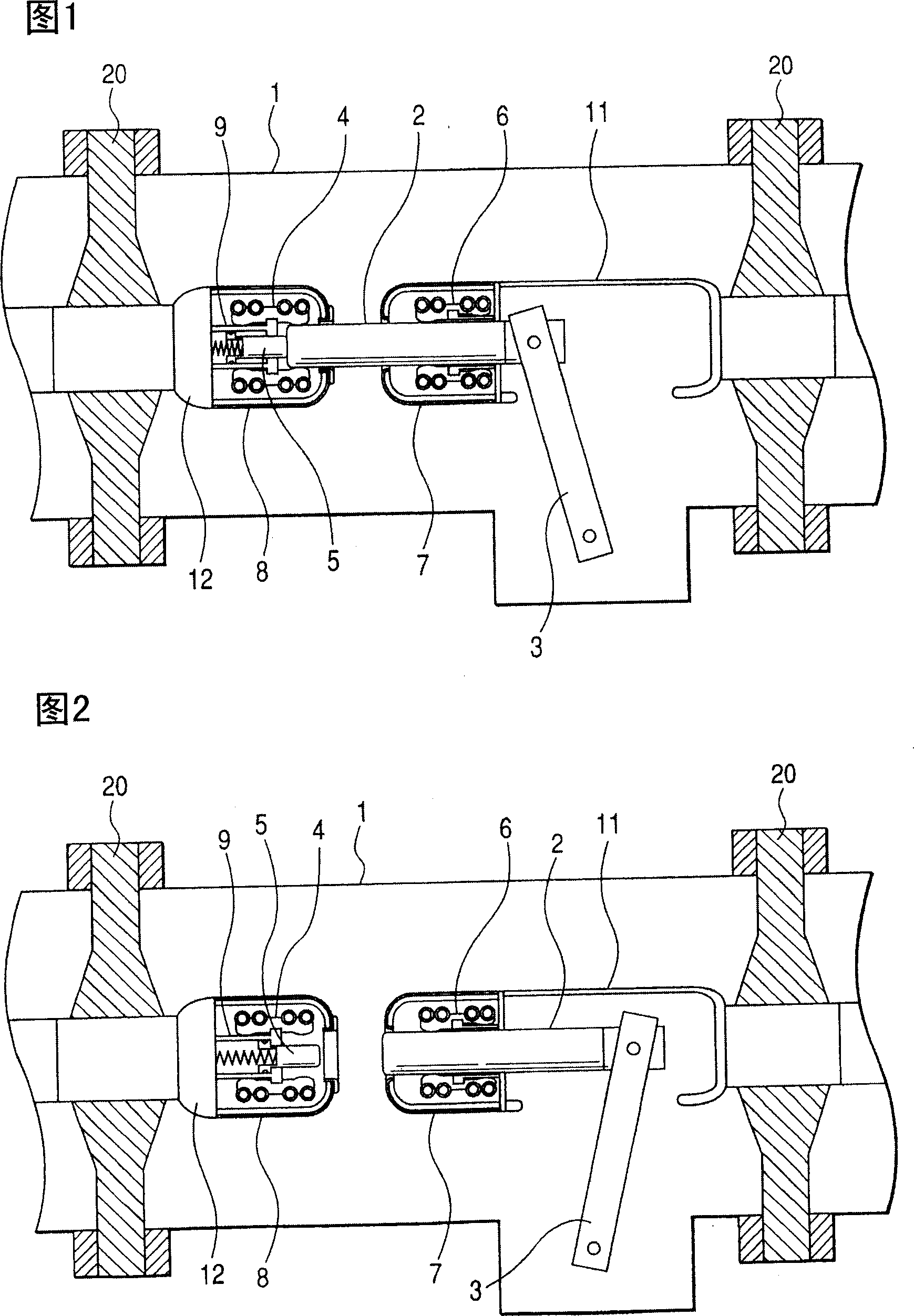
[0038] figure 1 It is a cross-sectional view showing an on state of a gas insulated switch according to an embodiment of the present invention.

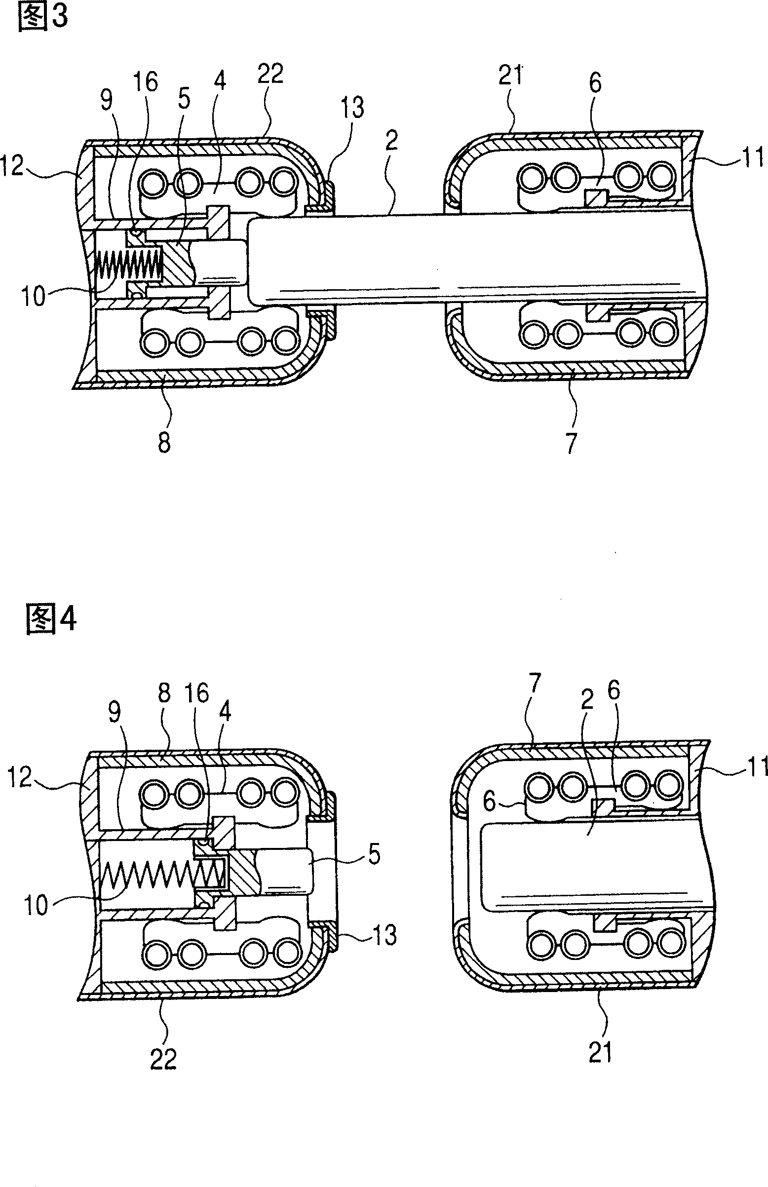
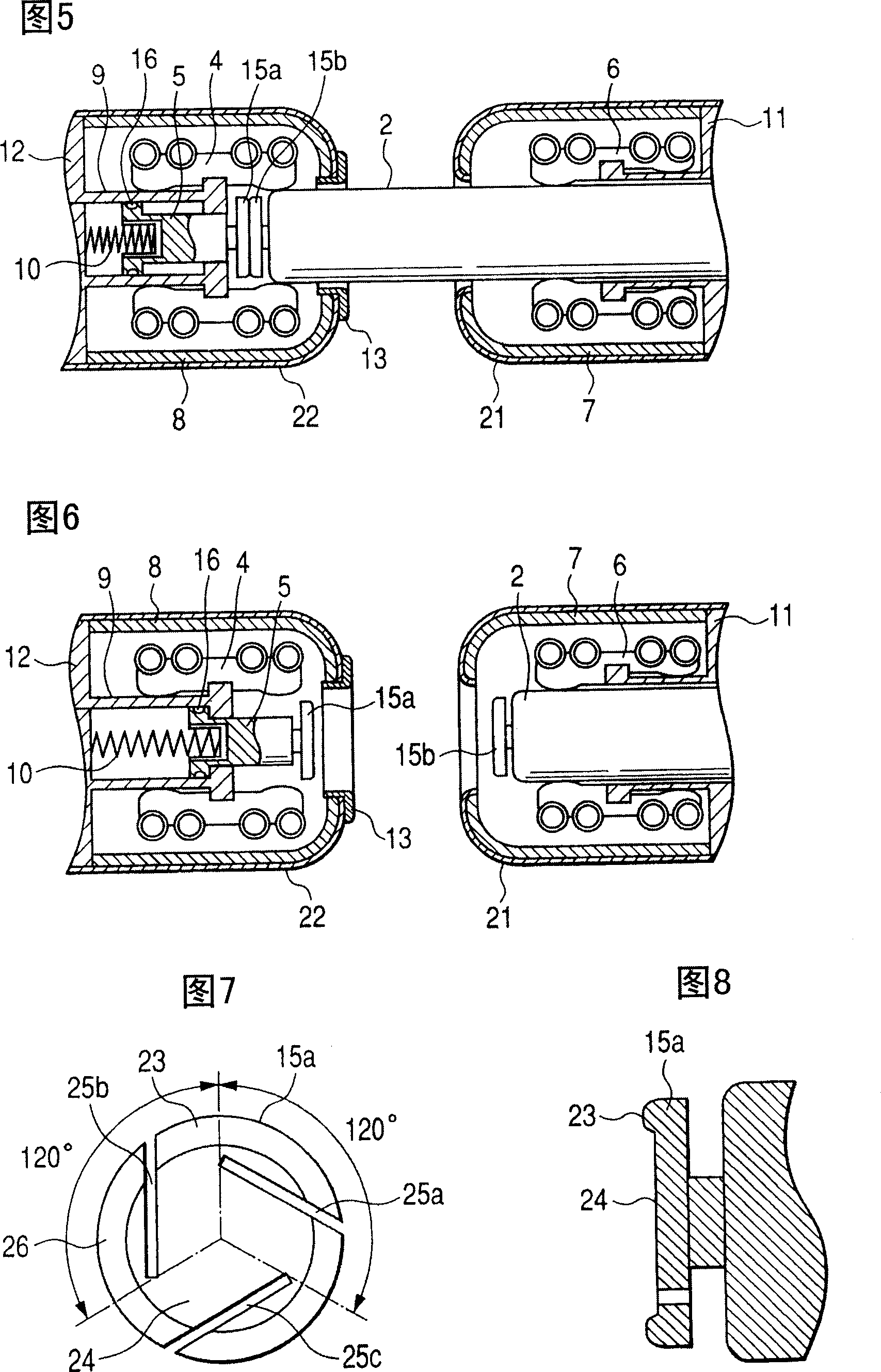
[0039] In the airtight container 1 enclosing an insulating gas, the high voltage conductors 11 , 12 are supported by insulating stays 20 in a state of being electrically insulated from the airtight container 1 . As the insulating gas sealed in the airtight container 1, electronegative gases such as SF gas above atmospheric pressure, air, nitrogen, carbon dioxide or their mixed gases, or electronegative gases and their mixed gases, etc. can be considered. The movable-side contact 6 and the fixed-side contact 4 for main energization are respectively installed on the opposite parts of the high-voltage conductors 11 and 12, and the movable-side electric field attenuation shields for attenuating the electric field ...


PUM


Abstract

To provide a gas-insulated switch for surely generating an arc between a tip of a needle and a tip of a fixed-side arc contact to prevent damage of a member disposed in the vicinity thereof. When an arc is formed between the needle 2 and the fixed-side arc contact 5, although the arc may be expanded in the direction of a sealed vessel to damage a fixed-side shield 8 for electric field relaxation or the like, a high dielectric strength voltage can be provided by protecting the fixed-side shield 8 for electric field relaxation from metal vapor and radiant heat generated by the arc without having a gas spraying means and by the fixed-side arc contact 5 unrelated to a resistor and restriction of the diameter of its tip and the final tip position.

Description

technical field [0001] The present invention relates to gas insulated switches, and more particularly to gas insulated switches having arcing contacts which ignite an arc when opened. Background technique [0002] The existing gas insulated switch is known to have a gas blowing mechanism for blowing insulating gas to the arc between the disconnected contacts, so as to improve the breaking performance of the loop current (for example, refer to Patent Document 1: Japanese Unexamined Patent Publication No. 5-266758 and Patent Document 2: Japanese Real Fair No. 6-43975); or be provided with a resistor connected in parallel with the main energized part and an arc contact connected to the resistor, so that when the current is disconnected , commutating the breaking current to the circuit of the resistor and the arc contact (for example, refer to Patent Document 3: Japanese Patent Laid-Open No. 2-236923 and Patent Document 4: Japanese Patent Laid-Open No. 3-129615). In addition, t...

Claims


Application Information

Patent Timeline
Patent Type & Authority Patents(China)
IPC IPC(8): H01H33/16H01H33/74
Inventor 六户敏昭八木桥义丰大森庄司山本直幸
Owner JAPAN AE POWER SYST
Learn More