Speaker device, audio control device, wall attached with speaker device

A technology of sound control and loudspeaker, which is applied in the direction of loudspeaker distribution signal, microphone, sound-generating equipment, etc., and can solve problems such as narrowing the room, uneven wave surface, and inability to store

A technology of sound control and loudspeaker, which is applied in the direction of loudspeaker distribution signal, microphone, sound-generating equipment, etc., and can solve problems such as narrowing the room, uneven wave surface, and inability to store

CN102449688AInactive Publication Date: 2012-05-09PANASONIC CORP

Image

  • Speaker device, audio control device, wall attached with speaker device
  • Speaker device, audio control device, wall attached with speaker device
  • Speaker device, audio control device, wall attached with speaker device

Examples


no. 1 Embodiment approach

[0253] The configuration of the sound control device according to the first embodiment will be described.

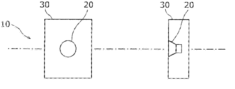
[0254] Figure 1a ~ Figure 1c It is a figure which respectively shows the structure of the speaker of the sound control apparatus of 1st Embodiment.

[0255] Figure 1a The left column of is a front view of installing the speaker unit 20 of the speaker 10 in the chamber 30, Figure 1a The right column of is its side view (section view).

[0256] The speaker unit 20 has a vibrating plate and a magnetic circuit. In this state, the sound in front of the vibrating plate and the sound behind the vibrating plate cancel each other out, and no bass is output. Therefore, it is accommodated in the cavity 30 . In addition, in Figure 1a ~ Figure 1c In the example shown above, this kind of airtight chamber 30 is used, but it is not limited to this, and a bass reflex method or the like may be used depending on the situation. That is, the speaker 10 is generally called a speaker ...

no. 2 Embodiment approach

[0338] The structure of the sound control device of the second embodiment will be described.

[0339] Figure 13a ~ Figure 13c It is a figure which shows the structure of the speaker of the sound control apparatus of 2nd Embodiment.

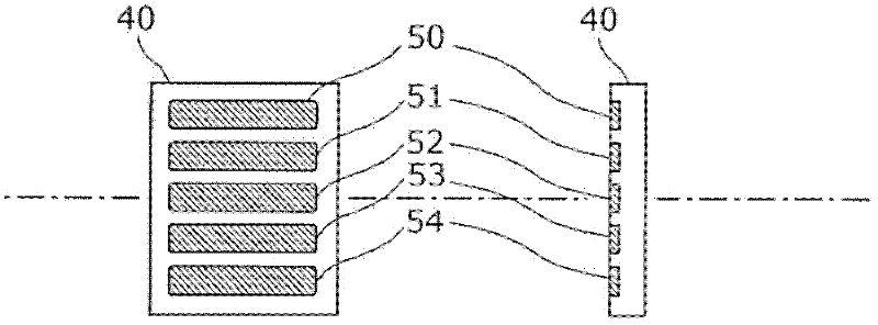
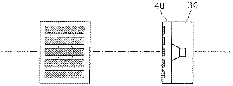
[0340] exist Figure 13a ~ Figure 13c in, means that the Figure 1b and Figure 1c The passive radiators 50-54 are replaced by a passive radiator 500. Additionally, other structures with Figure 1a ~ Figure 1c same.

[0341] The advantage in this case is that the number of passive radiators is significantly reduced and thus the costs are reduced.

[0342] Figure 14a ~ Figure 14c are respectively for the Figure 13a ~ Figure 13c A diagram showing an example of a speaker-error microphone configuration.

[0343] Here, the rigidity of the passive radiator 500 has an influence on the control. Ideally, the more preferable action of the passive radiator 500 is that the passive radiator 500 performs piston vibration. If the piston vibration is...


PUM


Abstract

Disclosed is a speaker (10) provided with a speaker unit (20), a passive radiator (50x) which is disposed on the front side of the speaker unit (20), and a cabinet (30) which is attached with the speaker unit (20), covers the rear side of the speaker unit (20), and is configured so that the space (30x) between the speaker unit (20) and the passive radiator (50x) is hermetically sealed, wherein the effective diaphragm area (50L) of the passive radiator (50x) is larger than the effective diaphragm area (20L) of the speaker unit (20).

Description

technical field [0001] The present invention relates to a sound control device, and more particularly, to a sound control device using a speaker of a size capable of being embedded in a wall or partition to reduce noise and improve music effects (presence, sound quality, etc.). And more specifically, it relates to a sound control device that can control the sound immediately in front of the speaker, and also conducts acoustic and electrical studies to suppress the amount of computation to a small amount when controlling the entire wall or partition. As a result, , can secure a wider control area surrounded by walls or partitions with less calculation load. Background technique [0002] For example, as a method of reducing uncomfortable noise, there has been an idea of ​​so-called active noise control that cancels noise by controlling speakers to reproduce sounds of opposite phases. There are examples of applications of active noise control in a restricted one-dimensional sp...

Claims


Application Information

Patent Timeline
09 May 2012
Publication
CN102449688A
IPC
G10K11/178; H04R1/28
CPC
G10K11/178; H04R3/005; H04R1/227; H04R1/28; H04R2227/001; H04R3/12; H04R2410/05; H04R1/2842
Inventors
狩野裕之