Interface circuit
An interface circuit and control circuit technology, applied in the direction of logic circuit coupling device, programmable logic circuit device, logic circuit connection/interface layout, etc. problem, to achieve good signal transmission characteristics and ensure the effect of signal transmission characteristics
- Summary
- Abstract
- Description
- Claims
- Application Information
AI Technical Summary
Problems solved by technology
Method used
Image

Examples
Embodiment approach 1
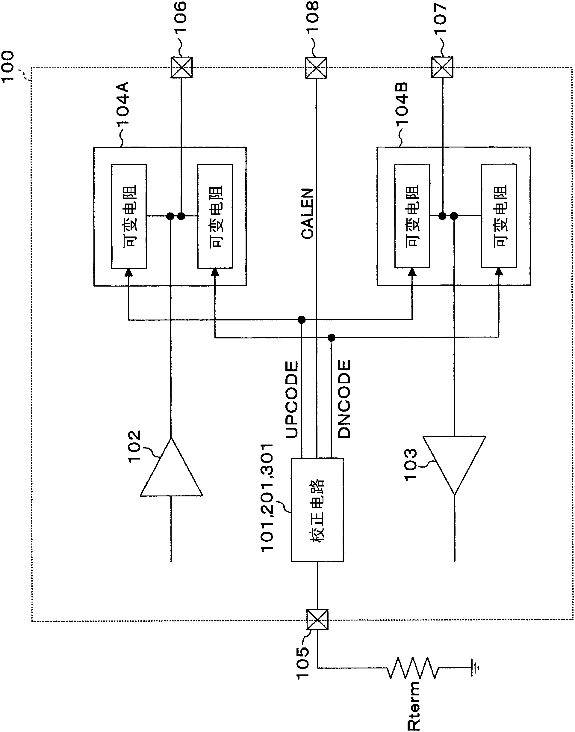
[0028] figure 1 It is a circuit diagram schematically showing the configuration of the interface circuit according to the first embodiment. figure 1The illustrated interface circuit 100 includes a transmitter circuit (transmitter circuit) 102, a receiver circuit (receiver circuit) 103, a transmission pad 106 connected to the data bus, and a reception pad 107 connected to the data bus. Between the transmitter circuit 102 and the transmission pad 106 and between the receiver circuit 103 and the reception pad 107 , variable resistors 104A and 104B functioning as active termination resistors of the bus are respectively provided. Furthermore, the interface circuit 100 includes a correction circuit 101 (201, 301) for correcting active termination resistance. The correction circuit 101 ( 201 , 301 ) is connected to an external reference resistor Rterm via a pad 105 . Then, after the calibration operation is performed, the resistance values of the variable resistance units 104A an...
Embodiment approach 2
[0064] The structure of the interface circuit according to Embodiment 2 is different from that shown in Embodiment 1. figure 1 It is the same, and its detailed description is omitted here.
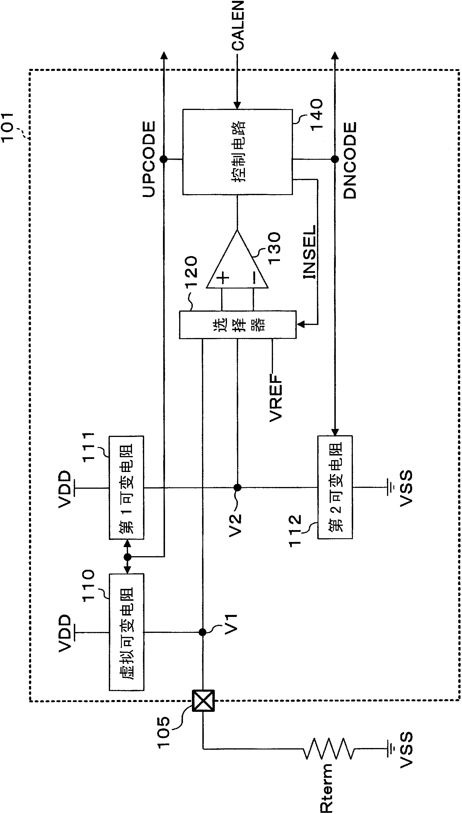
[0065] Figure 5 It is a circuit diagram showing the configuration of the correction circuit 201 according to this embodiment. exist Figure 5 in, right with image 3 Common constituents endowed with image 3 The same symbols are used, and their detailed descriptions are omitted here. exist Figure 5 Among them, 260 is a DA converter for offset correction of the comparator 130 , and 250 is an adder for adding the output of the DA converter 260 to the (+) input of the comparator 130 . The control circuit 240 outputs the offset correction signal OFFCAN supplied to the DA converter 260 in addition to the first and second variable resistor control signals UPCODE, DNCODE, and the selector control signal INSEL. The DA converter 260 converts the offset correction signal OFFCAN into an anal...
Embodiment approach 3
[0090] The structure of the interface circuit according to Embodiment 3 is the same as that shown in Embodiment 1. figure 1 It is the same, and its detailed description is omitted here.
[0091] Figure 6 It is a circuit diagram showing the configuration of the correction circuit 301 according to this embodiment. exist Figure 6 in, right with image 3 Common constituents endowed with image 3 The same symbols are used, and their detailed descriptions are omitted here. exist Figure 6 Among them, 380 is a temperature detection unit, and 370 is a temperature correction table. The temperature detection unit 380 includes a temperature-voltage conversion element 381 and comparators 331 and 332 for comparing the output of the temperature-voltage conversion element 381 with mutually different temperature detection reference voltages VREFH and VREFL. Comparators 331 and 332 constitute a comparison unit for temperature detection. Reference voltage VREFH is a voltage level for ...
PUM
 Abstract
Description
Claims
Application Information
 - R&D
- Intellectual Property
- Life Sciences
- Materials
- Tech Scout
- Unparalleled Data Quality
- Higher Quality Content
- 60% Fewer Hallucinations
Browse by: Latest US Patents, China's latest patents, Technical Efficacy Thesaurus, Application Domain, Technology Topic, Popular Technical Reports.
© 2025 PatSnap. All rights reserved.Legal|Privacy policy|Modern Slavery Act Transparency Statement|Sitemap|About US| Contact US: help@patsnap.com