
Zipper slider and zipper head with same

A technology of sliders and zippers, applied in the direction of application, sliding fastener components, fasteners, etc., can solve the problems of complex assembly process and complex structure of sliders, and achieve the effects of simple structure, improved safety, and easy assembly

Active Publication Date: 2012-05-16
FUJIAN SBS ZIPPER SCI & TECH CO LTD
View PDF5 Cites 9 Cited by
  • Summary
  • Abstract
  • Description
  • Claims
  • Application Information

AI Technical Summary

Problems solved by technology

[0003] But, the slider of the self-locking zipper puller of the prior art that can replace the pull tab must include a gap closure in order to realize the replaceable function of the pull tab, the number of required parts is large, the structure is more complicated, and because The structure is complicated, so the assembly process of the slider of the self-locking zipper puller is also relatively complicated

Method used


Image

  • Zipper slider and zipper head with same
  • Zipper slider and zipper head with same
  • Zipper slider and zipper head with same

Examples


Embodiment Construction

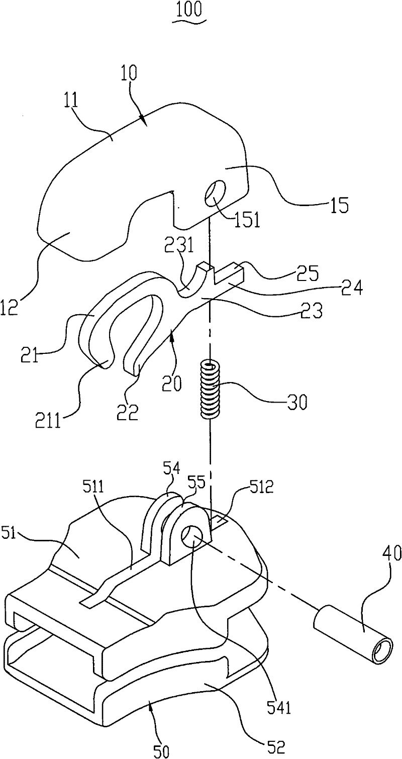
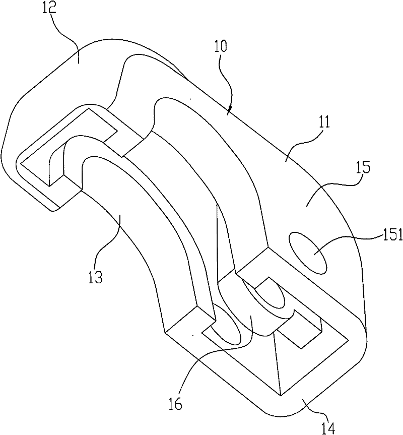
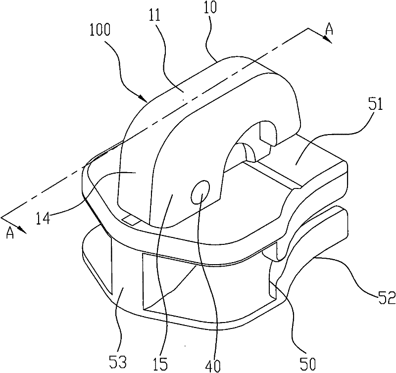
[0037] see figure 1 , figure 2 and image 3 , figure 1 It is an exploded perspective view of the first embodiment of the zipper slider 100 of the present invention. The zipper slider 100 includes a cap 10 , a self-locking element 20 , an elastic element 30 , a circular tube 40 and a slider body 50 . The self-locking element 20 is placed on the slider body 50 . The cap 10 is fixed on the slider body 50 through the circular tube 40 and is covered on the self-locking element 20 . The elastic element 30 is fixed between the cap 10 and the slider body 50 .

[0038] The slider body 50 includes an upper wing plate 51, a lower wing plate 52 and a guide post 53, the upper wing plate 51 and the lower wing plate 52 are connected by the guide post 53 to form a substantially Y-shaped slideway For the chain teeth (not shown) of a zipper to pass through. An elongated groove 511 and a through hole 512 are disposed on the upper wing 51 , the through hole 512 communicates with the groove...


PUM


Abstract

The invention relates to a zipper slider and a zipper head with the same. The zipper slider comprises a cap, a self-locking element, an elastic element and a slider body, wherein the slider body comprises an upper wing plate and a guide post; the self-locking element is arranged on the upper wing plate of the slider body; one end of the elastic element is fixed between the slider body and the cap; the other end of the elastic element is elastically pressed against the self-locking element; the cap is fixed on the upper wing plate of the slider body; the self-locking element comprises a horse hook part, a pivot joint part and a pressing part; the pivot joint part is positioned between the pressing part and the horse hook part; a pivoting part is arranged in the cap; the self-locking element is in pivot joint with the pivoting part of the cap through the pivot joint part; a through hole is formed on the slider body corresponding to the pressing part; and the pressing part is communicated with the outside of the slider body through the through hole. The invention has the advantages that: the zipper slider and the zipper head have simple structures and are convenient to assemble.

Description

technical field [0001] The invention relates to a zipper slider and a zipper slider using the zipper slider, in particular to a self-locking zipper slider with a replaceable slider and a zipper slider using the zipper slider. Background technique [0002] At present, there are various self-locking zipper pullers with replaceable sliders. For example, the patent No. 4,829,638 published on May 16, 1989 discloses a slider for a self-locking zipper pull with a detachable pull tab in this prior art. The zipper slider has an upper wing and a lower wing, and the upper and lower wings are connected by a guide post. The upper wing plate is located above the guide column and is provided with a connecting lug, the front end of an arc-shaped pull tab holder is fixed on the connecting lug, and a gap is formed between its rear end and the upper wing plate. The zipper slider also includes a self-locking horse hook and a gap closure, the self-locking horse hook is used to complete the sel...

Claims


Application Information

Patent Timeline
Patent Type & Authority Applications(China)
IPC IPC(8): A44B19/30
Inventor 高秀忠
Owner FUJIAN SBS ZIPPER SCI & TECH CO LTD
Learn More