Secondary ejecting mechanism

A technology of secondary ejection and plate ejection, which is applied in the field of ejection mechanism, can solve problems such as small ejection force, product breakage and strain, complex mechanism, etc., and achieve large ejection force, good reliability and durability, and structural simple effect

Inactive Publication Date: 2012-05-16
SUZHOU MITAC PRECISION TECH
View PDF0 Cites 2 Cited by
  • Summary
  • Abstract
  • Description
  • Claims
  • Application Information

AI Technical Summary

Problems solved by technology

[0003] The existing secondary ejection mechanisms include: the secondary ejection mechanism in the form of a hook, which is relatively complicated; the secondary ejection mechanism using a resin shutter, which is easy to wear, easy to fail and has a small ejection force ;Using the secondary ejection mechanism in the form of spring, this mechanism is generally used for partial secondary ejection of a single movable insert, but after the spring is compressed, because there is no starting force, it cannot be ejected synchronously with the product, causing the product to break. hurt

Method used


Image

  • Secondary ejecting mechanism
  • Secondary ejecting mechanism
  • Secondary ejecting mechanism

Examples


Embodiment Construction

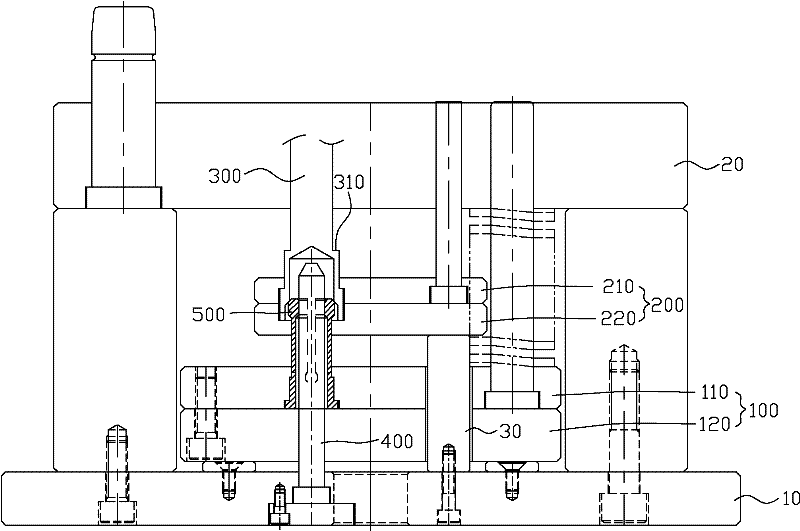
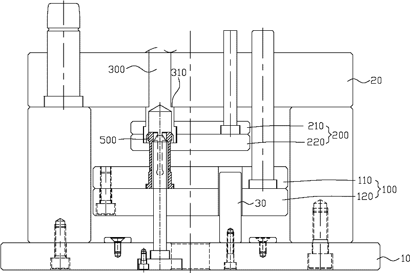
[0016] see figure 1 As shown, it shows a schematic diagram of the secondary ejection mechanism of the present invention.

[0017] The secondary ejection mechanism of the present invention is applied in a mold, and the mold includes: a lower fixing plate 10, a male template 20, a female template (not shown), and a support rod 30, and the secondary ejection mechanism includes:

[0018] A first ejector plate 100, which is located on the lower fixing plate 10 of the above-mentioned mould, the first ejector plate 100 is provided with a first upper ejector plate 110 and a first lower ejector plate 120;

[0019] A second ejector plate 200, which is located on the support rod 30 of the above-mentioned mold, the second ejector plate 200 is provided with a second upper ejector plate 210 and a second lower ejector plate;

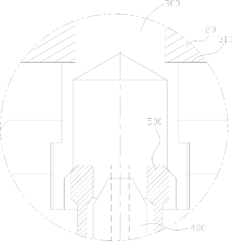
[0020] A limiting rod 300, one end of which is arranged in the above-mentioned second ejector plate 200, and the other end is arranged in the mother template (not sho...


PUM


Abstract

The invention relates to a secondary ejecting mechanism applied in dies. The secondary ejecting mechanism comprises: a first ejector plate that is mounted on a lower fixed plate of a die and is provided with a first upper ejector plate and a first lower ejector plate; a second ejector plate that is disposed on a support bar of the die and provided with a second upper ejector plate and a second lower ejector plate; a limiting bar equipped with a damping part, with one end of the limiting bar positioned in the second ejector plate and the other end positioned in a female template of the die; a control bar, which has one end installed in the lower fixed plate of the die and the other end installed in the second ejector plate, as well as an outer rim sleeved with an elastic sleeve, one end of which is mounted in the first ejector plate and the other end of which is positioned in the limiting bar. The secondary ejecting mechanism of the invention has the advantages of simple structure, great ejection force, as well as good reliability and durability.

Description

【Technical field】 [0001] The invention relates to an ejection mechanism, in particular to a secondary ejection mechanism. 【Background technique】 [0002] At present, when the mold is producing plastic products, the special product structure requires secondary ejection or multiple ejection. [0003] The existing secondary ejection mechanisms include: the secondary ejection mechanism in the form of a hook, which is relatively complicated; the secondary ejection mechanism using a resin shutter, which is easy to wear, easy to fail and has a small ejection force ;Using the secondary ejection mechanism in the form of spring, this mechanism is generally used for partial secondary ejection of a single movable insert, but after the spring is compressed, because there is no starting force, it cannot be ejected synchronously with the product, causing the product to break. hurt. [0004] In view of this, it is necessary to develop a new type of secondary ejection mechanism, which has ...

Claims


Application Information

Patent Timeline
Patent Type & Authority Applications(China)
IPC IPC(8): B29C33/44
Inventor 陈发启
Owner SUZHOU MITAC PRECISION TECH
Why Eureka
Try Eureka