System for determining EGR degradation

一种EGR冷却器、指示的技术,应用在监视EGR系统领域,能够解决EGR系统劣化、不连续、误报等问题,达到改善参数估算、简化模型调校的效果

Inactive Publication Date: 2012-05-16
FORD GLOBAL TECH LLC
View PDF13 Cites 2 Cited by
  • Summary
  • Abstract
  • Description
  • Claims
  • Application Information

AI Technical Summary

Problems solved by technology

However, adjusting the position of the two-state cooling control valve in some modeled systems can result in discontinuities making it difficult to assess whether the operation of the EGR system is degraded
If the discontinuity caused by switching the cooling control valve is not properly addressed, it can lead to false positive or false negative indications of EGR system degradation

Method used


Image

  • System for determining EGR degradation
  • System for determining EGR degradation
  • System for determining EGR degradation

Examples


Embodiment Construction

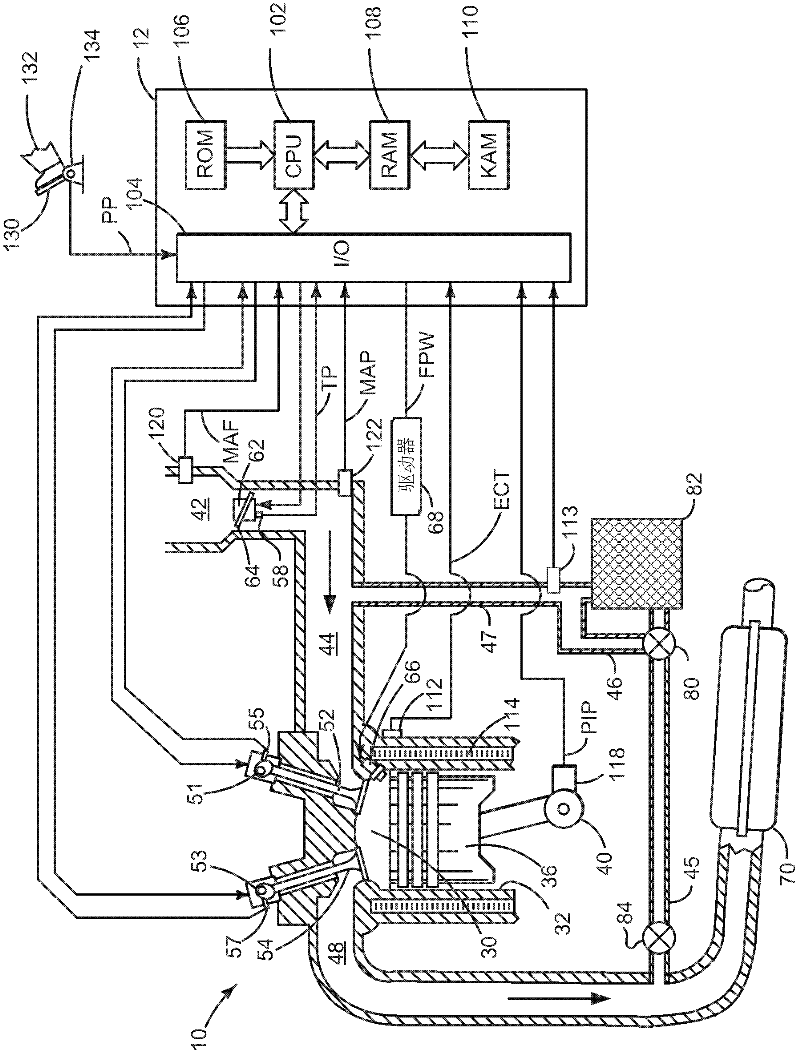
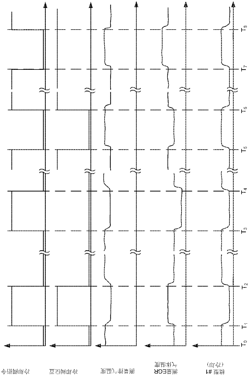
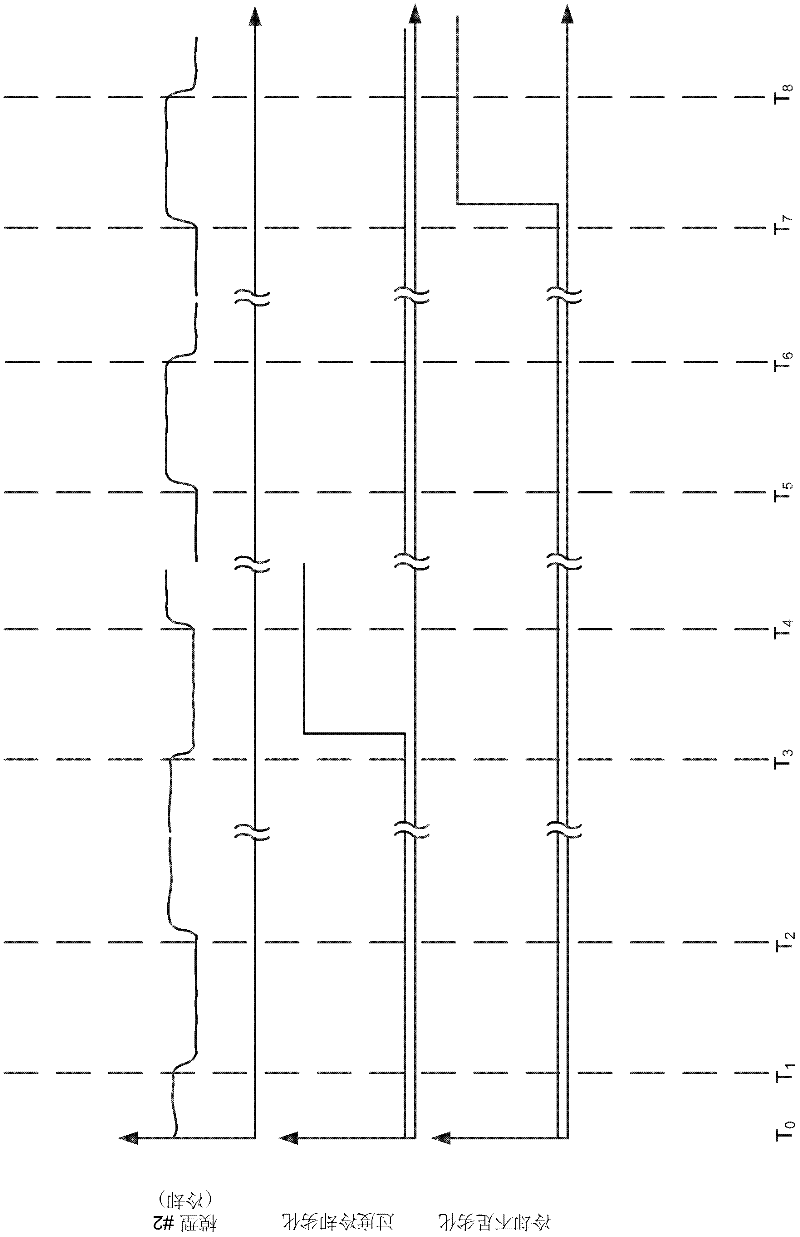
[0024] The present invention relates to monitoring and determining EGR system degradation. In one example, the EGR system is adapted such as figure 1 Diesel engine shown in . However, the present invention may also provide advantages for gasoline and alternative fuel engines. Accordingly, the present invention is not limited to a particular type of engine or a particular EGR system configuration. Figure 2-3 Displays when the engine and EGR system are Figure 4 Analog related signals when the method in run.

[0025] refer to figure 1 , consisting of multiple cylinders ( figure 1 One cylinder of which is shown in ) is controlled by an electronic engine controller 12 . Engine 10 includes combustion chamber 30 and cylinder walls 32 with piston 36 positioned therein and connected to crankshaft 40 . Combustion chamber 30 is shown communicating with intake manifold 44 and exhaust manifold 48 via respective intake valve 52 and exhaust valve 54 . Each intake and exhaust valve ...


PUM


Abstract

A system for improving operation of an EGR system is presented. The system provides distinct models to estimate EGR temperature in response to a valve position. In one example, the system can judge EGR system operation when a state of a control valve is adjusted during driving conditions.

Description

technical field [0001] The present invention relates to methods and systems for improving the operation and diagnostics of exhaust gas recirculation (EGR) systems. The method may be particularly applicable to engines with cooled EGR. Background technique [0002] EGR has long been applied to engines to control NOx emissions and reduce engine pumping work. EGR can reduce engine pumping work by increasing intake manifold pressure. EGR can reduce NOx emissions by reducing the peak combustion temperature in the cylinder. Currently, the EGR system has begun to cool the EGR to further reduce the combustion temperature in the cylinder, thereby further reducing engine NOx emissions. However, cooled EGR is not necessary under all engine operating conditions, so some EGR systems provide both unregulated and cooled EGR. [0003] While EGR systems can assist in reducing engine emissions and improving engine operation by providing unregulated and cooled EGR, such systems present chal...

Claims


Application Information

Patent Timeline
Patent Type & Authority Applications(China)
IPC IPC(8): F02M25/07
CPCF02M25/0754F02D41/0072F02D2041/0067F02D41/1446F02M25/0738F02M25/0731Y02T10/47F02D2041/007F02M25/0702F02M25/0727F02M25/0728F02D41/221F02M26/23F02M26/25F02M26/28F02M26/33F02M26/47F02M26/49Y02T10/40
Inventor M·C·法默
Owner FORD GLOBAL TECH LLC
Why Eureka
Try Eureka