Outer adapter

An adapter and detector technology, applied in circuit breaker testing, impedance networks, electrical components, etc., can solve problems such as increased power consumption, inability to control circuit 5 to provide sufficient power, and electronic switch 1 voltage reduction, etc., to reduce power consumption. Effect

Inactive Publication Date: 2012-05-16
KAWAMURA ELECTRIC INC
View PDF4 Cites 2 Cited by
  • Summary
  • Abstract
  • Description
  • Claims
  • Application Information

AI Technical Summary

Problems solved by technology

However, when the impedance of the analog load 55 is set to be greater than the impedance of the electronic switch 1, as Figure 8 As shown, the voltage across the two ends of the electronic switch 1 decreases, unable to pr

Method used


Image

  • Outer adapter
  • Outer adapter
  • Outer adapter

Examples


Embodiment Construction

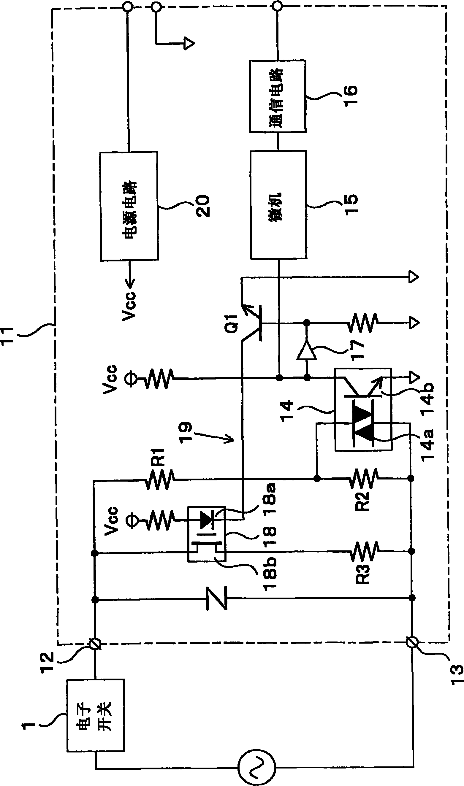
[0021] Embodiments of the present invention will be described below with reference to the drawings. like figure 1 As shown, the external adapter 11 of this embodiment has: two input terminals 12, 13 connected to the electronic switch 1; / OFF) state photocoupler 14. In addition, the electronic switch 1 is provided with a contact 4 and a control circuit 5 (refer to Figure 5 ), the contact 4 uses a semiconductor switching element.

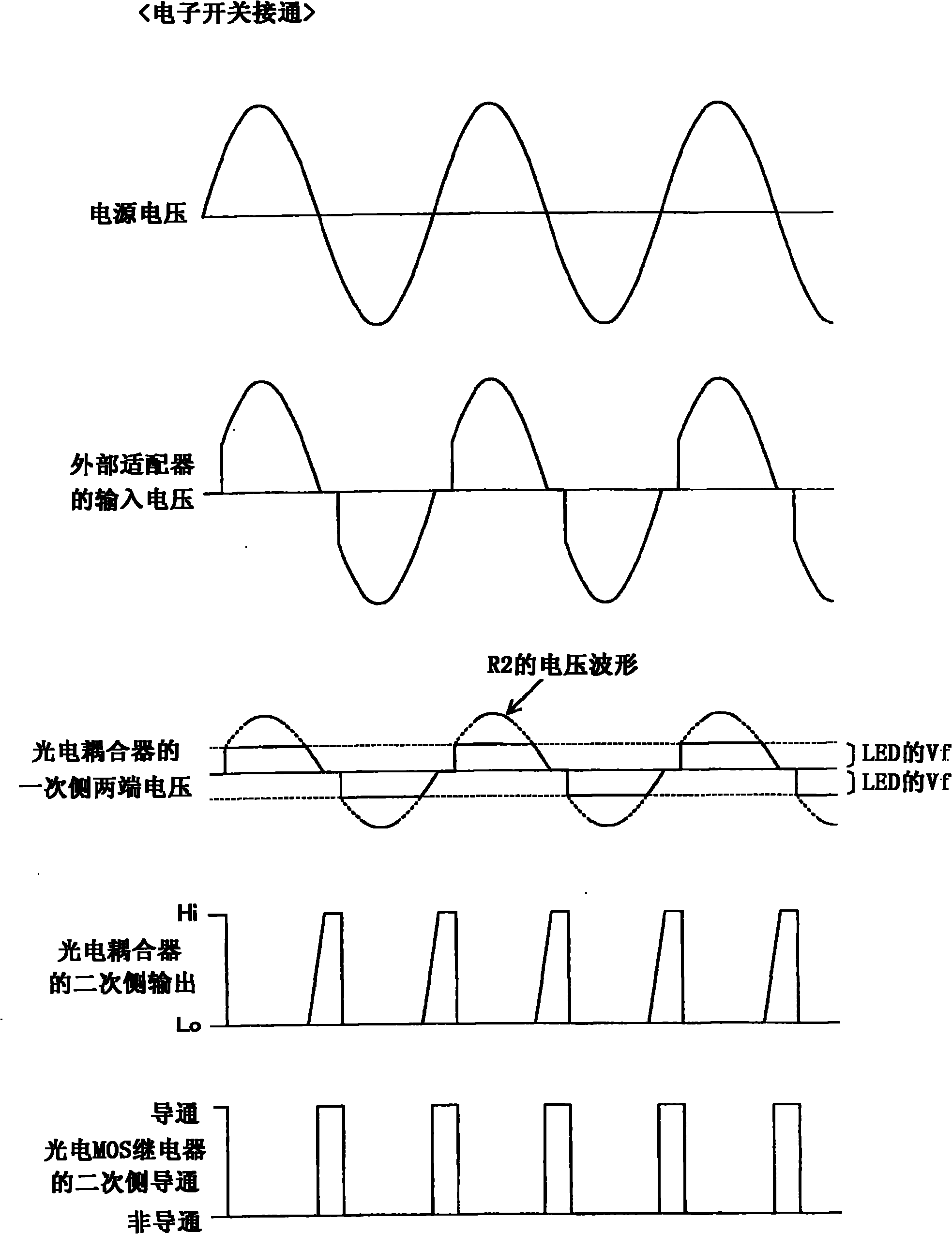
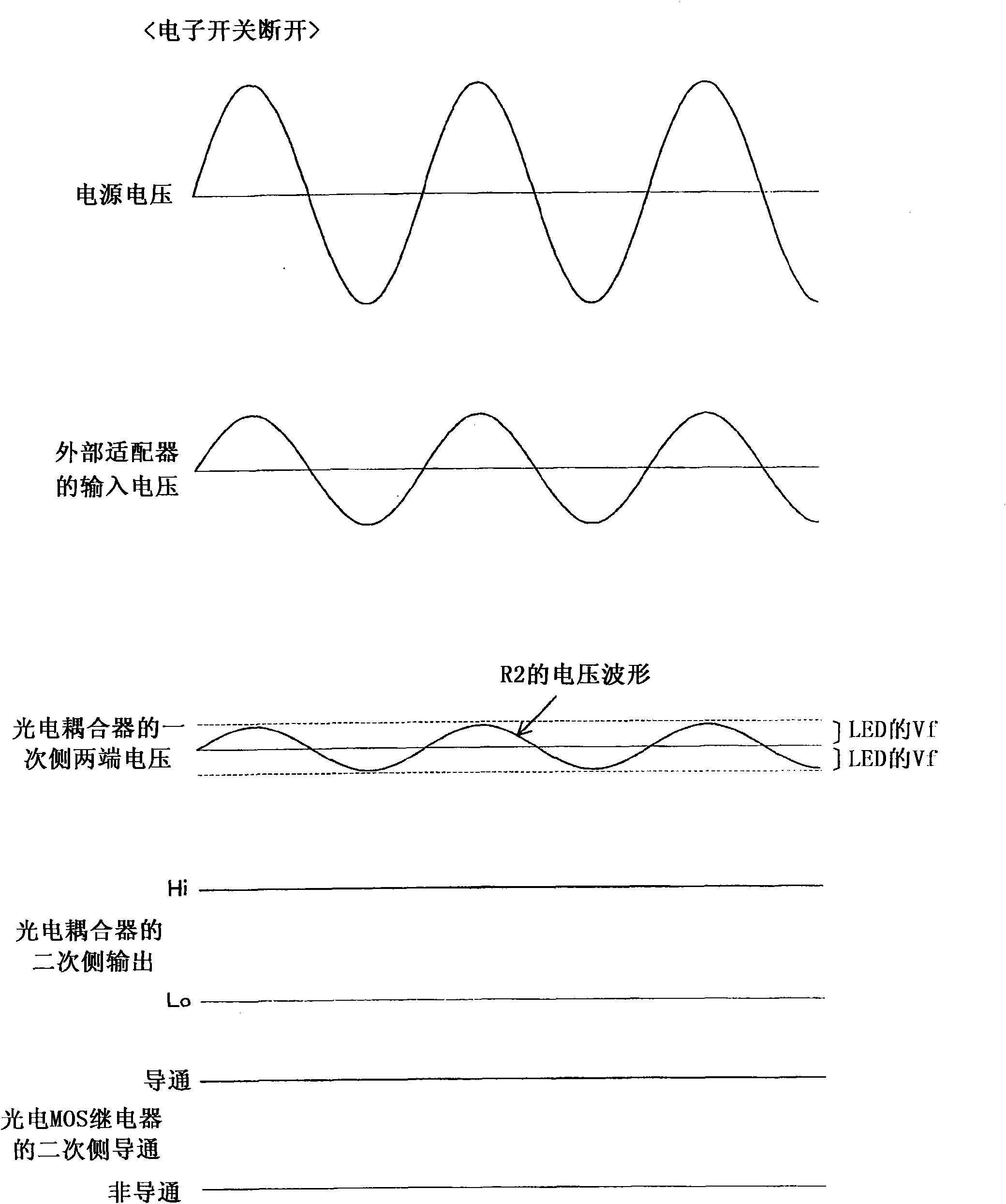
[0022] Between the input terminals 12 and 13, the first and second voltage-dividing resistors R1 and R2 for dividing the input voltage are arranged in series, and both ends of the second voltage-dividing resistor R2 are connected to the primary-side LED of the photocoupler 14 Section 14a. In addition, the photocoupler 14 detects the ON state of the electronic switch 1 when the voltage across the second voltage dividing resistor R2 exceeds the forward voltage Vf of the LED portion 14a, and otherwise detects the OFF state of the electronic switch 1...


PUM


Abstract

An outer adapter can feasibly detect switching on/off state of a two-wire type electronic switch through a circuit with little power consumption. The outer adapter (11) is provided with two input terminals (12,13) which are connected with an electronic switch (1). Voltage dividing resistors (R1,R2) perform voltage dividing on input voltage. According to the voltage over two ends of the voltage dividing resistor (R2), a photoelectric coupler (14) detects the switching on/off state of the electronic switch (1). An impedance adjusting circuit (19) is provided with the following components: an adjusting resistor (R3) which is equipped between the input terminals (12,13), a transistor (Q1) which responds to output of the photoelectric coupler (14) and switches to switch on/off the adjusting resistor (R3), and a photoelectric MOS relay (18). Input impedance of the adapter (11) is adjusted to a relatively high value at a contact conduction state of the electronic switch (1), and is adjusted to a relatively low value at a contact non-conduction state.

Description

technical field [0001] The present invention relates to an external adapter for externally detecting a contact signal of a two-wire electronic switch and constructing various systems. Background technique [0002] Two-wire electronic switches used in light switches, occupancy sensors, etc. are typically such as Figure 5 As shown, the two terminals 2 and 3 are used both for the output of the contact signal and for the power supply to the control circuit 5 . Semiconductor switching elements such as triacs and thyristors are widely used for the contact 4 of the electronic switch 1 . Semiconductor switching elements have the advantage of being able to reduce the circuit current during conduction without having to worry about contact wear. and if Figure 6 As shown, when the electronic switch 1 is turned on, power can also be supplied to the control circuit 5 by utilizing the non-conduction angle of the switching element. [0003] In such an electronic switch 1 , a weak curre...

Claims


Application Information

Patent Timeline
IPC IPC(8): H03H7/38G01R31/327
Inventor 加藤昌幸
Owner KAWAMURA ELECTRIC INC
Why Eureka
Try Eureka