
MEMS (Micro Electronic Mechanical System) capacitive microphone without back polar plate and manufacture method thereof

A technology of capacitive microphone and back plate, which is applied in the direction of electrical components, electrostatic transducers, microphones, sensors, etc., can solve the problems of reducing the reliability of the microphone, the microphone has no output signal, etc., achieve small air gap, improve reliability, The effect of simplifying the preparation process steps

Inactive Publication Date: 2012-05-16
ACUTI MICROSYST
View PDF11 Cites 14 Cited by
  • Summary
  • Abstract
  • Description
  • Claims
  • Application Information

AI Technical Summary

Problems solved by technology

[0008] However, due to the high bias voltage between the substrate and the vibrating membrane when the microphone is working normally, when the gap between the substrate and the vibrating membrane becomes smaller, the electrostatic force between the subs

Method used


Image

  • MEMS (Micro Electronic Mechanical System) capacitive microphone without back polar plate and manufacture method thereof
  • MEMS (Micro Electronic Mechanical System) capacitive microphone without back polar plate and manufacture method thereof
  • MEMS (Micro Electronic Mechanical System) capacitive microphone without back polar plate and manufacture method thereof

Examples


Embodiment Construction

[0021] The following will clearly and completely describe the technical solutions in the embodiments of the present invention with reference to the accompanying drawings in the embodiments of the present invention. Obviously, the described embodiments are only some, not all, embodiments of the present invention. Based on the embodiments of the present invention, all other embodiments obtained by persons of ordinary skill in the art without making creative efforts belong to the protection scope of the present invention.

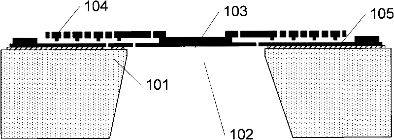
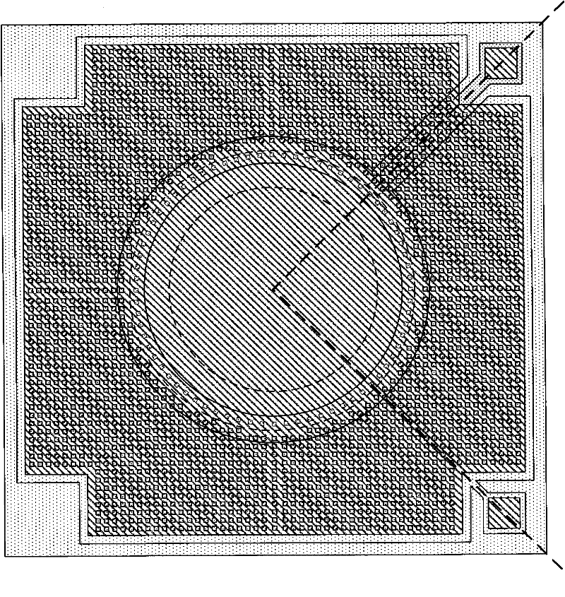
[0022] see figure 1 As shown, it is a cross-sectional view of a MEMS capacitive microphone without a back plate according to an embodiment of the present invention, including: a substrate 101, a back cavity 102, a first plate 105 and a second plate 104 of a capacitor, and a vibrating membrane 103 and lead wires (not shown in the figure), wherein, the back cavity 102 is located below the vibrating membrane 103; the vibrating membrane 103 is arranged on the subs...


PUM


Abstract

The invention discloses an MEMS (Micro Electronic Mechanical System) capacitive microphone without a back polar plate and a manufacture method thereof. The MEMS capacitive microphone comprises a substrate, a back cavity, a first polar plate of a capacitor, a second polar plate of the capacitor, a vibration diaphragm and leads, wherein the back cavity is positioned on the substrate; the vibration diaphragm is arranged on the substrate and is used for detecting acoustical vibration and converting the acoustical vibration into displacement; the first polar plate is arranged on the substrate; the second polar plate is arranged on the vibration diaphragm and is provided with bulges which are used for preventing the first polar plate and the second polar plate from being mutually sucked; and the leads are used for leading out the first polar plate and the second polar plate so as to form electric connection.

Description

technical field [0001] The present invention relates to a micro-electromechanical system (Micro-electromechanical Systems, MEMS) of silicon technology, in particular to a MEMS capacitive microphone without a back plate and a preparation method thereof. Background technique [0002] The general silicon microphone design adopts a double-layer or multi-layer film design, including a sensitive film and a back electrode film with a large number of sound holes. The manufacturing process of double-layer and multi-layer film designs is relatively complicated, and there are problems such as "soft back pole" and adhesion. For this reason, a single-layer film design has been proposed. Refer to [0003] Chinese patent application No. 200480044734.4 discloses a silicon-based microphone element and its manufacturing method. The microphone sensing element has a diaphragm adjoining the perforated plate on each side and corner. The diaphragm is positioned over one or more back holes formed...

Claims


Application Information

Patent Timeline
IPC IPC(8): H04R19/04H04R31/00
Inventor 杨少军
Owner ACUTI MICROSYST
Learn More