Power-supply cord arrangement structure
A technology for power cords and electrical equipment, which is applied to the circuit layout of supporting structures, electrical equipment shells/cabinets/drawers, circuits, etc., which can solve problems such as metal fatigue and accelerated power cord degradation time, so as to prolong the service life and improve Convenience, effect of delaying deterioration time
- Summary
- Abstract
- Description
- Claims
- Application Information
AI Technical Summary
Problems solved by technology
Method used
Image
Examples
no. 1 approach
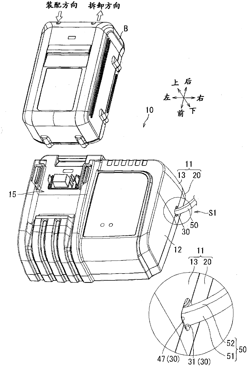
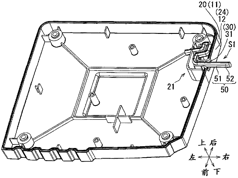
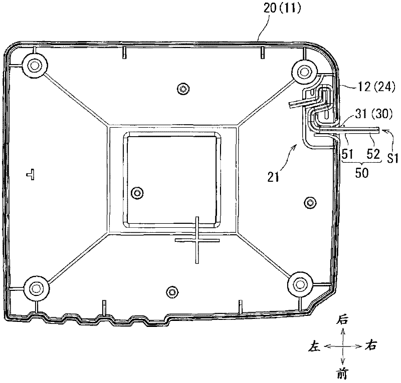
[0040] Hereinafter, a first embodiment of an arrangement structure of a power cord included in an electric device according to the present invention will be described with reference to the drawings. In addition, in the arrangement|positioning structure S1 of the power cord of embodiment demonstrated below, the charger is shown as an example and demonstrated as an electric device equipped with a power cord. figure 1 The appearance of this charger 10 as an electric device is shown in a perspective view. In addition, in the following description, the direction of "up, down, front, back, left, and right" is specified based on the assembly direction of the battery pack B as shown in the illustration. That is, in the charger 10 , the mounting side of the battery pack B is defined as the upper side, and the direction in which the battery pack B is slid when the battery pack B is mounted is defined as the front side. in addition, figure 1 The illustrated battery pack B is configured...
no. 2 approach
[0074] The arrangement structure S1 forming the power supply line 50 of the above-mentioned first embodiment may also be configured as the following second embodiment. In addition, in the arrangement structure S2 forming the power supply line 50 of the second embodiment described below, the parts configured in the same manner as those forming the arrangement structure S1 of the power supply line 50 of the first embodiment described above are assigned the same reference numerals. Description omitted.
[0075] Figure 7 It is a schematic schematic diagram showing the second embodiment for comparison with the lead-out hole 30 of the first embodiment described above. In addition, in Figure 7 In the drawing, in order to show the action point of the pulling load in the power cord 50 , the lead-out hole main body 31A (lead-out hole 30A) and the power cord 50 are schematically simplified and shown.
[0076] which is, Figure 7 The upper left figure of ] is a diagram of a state wh...
no. 3 approach
[0080] The arrangement structure S1 forming the power line 50 of the above-mentioned first embodiment may also constitute the following third embodiment. In addition, in the arrangement structure S3 forming the power supply line 50 of the third embodiment described below, the parts configured in the same manner as those forming the arrangement structure S1 of the power supply line 50 of the first embodiment described above are assigned the same reference numerals. Description omitted.
[0081] Figure 8 It is a schematic diagram showing a third embodiment for comparison with the extraction hole 30 of the first embodiment described above. In addition, in Figure 8 In the drawing, in order to show the action point of the pulling load on the power cord 50 , the lead-out hole main body 31B (lead-out hole 30B) and the power cord 50 are schematically simplified and shown.
[0082] which is, Figure 8 The upper left figure of ] is a diagram showing a case where the power cord 50 ...
PUM
 Abstract
Description
Claims
Application Information
 - R&D
- Intellectual Property
- Life Sciences
- Materials
- Tech Scout
- Unparalleled Data Quality
- Higher Quality Content
- 60% Fewer Hallucinations
Browse by: Latest US Patents, China's latest patents, Technical Efficacy Thesaurus, Application Domain, Technology Topic, Popular Technical Reports.
© 2025 PatSnap. All rights reserved.Legal|Privacy policy|Modern Slavery Act Transparency Statement|Sitemap|About US| Contact US: help@patsnap.com


