District energy sharing system

A technology for sharing system, district energy, applied in district heating system, heating system, energy-saving heating/cooling, etc., can solve problems such as hindering efficient operation

Inactive Publication Date: 2012-05-16
DEC DESIGN MECHANICAL CONSULTANTS
View PDF7 Cites 20 Cited by
  • Summary
  • Abstract
  • Description
  • Claims
  • Application Information

AI Technical Summary

Problems solved by technology

Efficient operation is also hindered when some building heat pumps are heating and some are cooling because there will be substantial temperature v

Method used


Image

  • District energy sharing system
  • District energy sharing system
  • District energy sharing system

Examples


Embodiment Construction

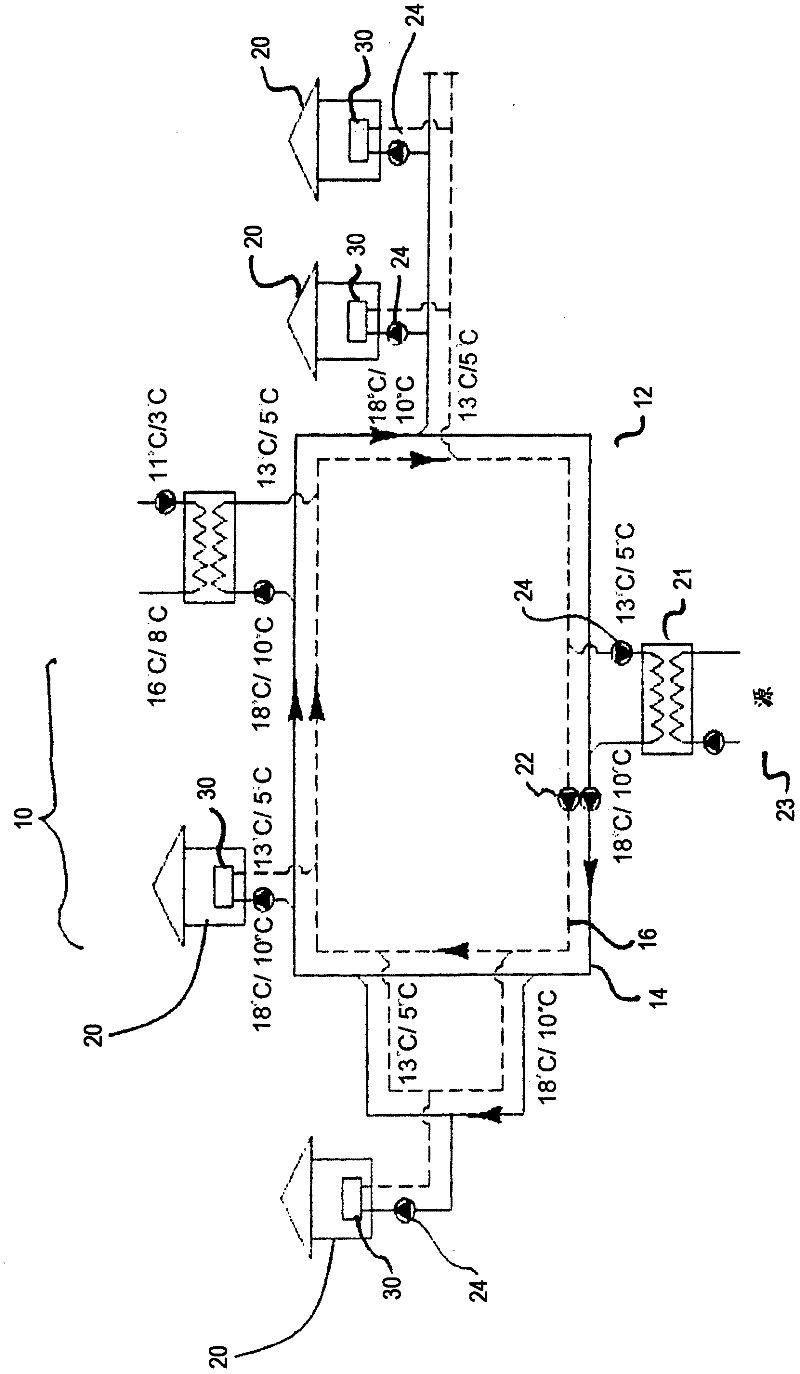
[0029] refer to image 3 And according to one embodiment, a district energy sharing system (DESS) 10 includes: a thermal energy loop 12 that circulates and stores thermal energy in water; at least one customer building 20 that is thermally coupled to and diverts some of the thermal energy from the loop 12 (“cooling source ”) and / or deposit some thermal energy (“heat source”) into loop 12 (note: customer building 20 shown in this figure is shown drawing thermal energy only from loop 12 and therefore both operating as a sink); and at least A thermal server plant 21 , can be thermally coupled to external heat and / or cooling sources (eg geothermal underground sources) and its function is to maintain thermal balance within the DESS 10 . DESS 10 may also include a networked control and monitoring system (not shown) for regulating, measuring and optimizing thermal energy delivery during system operation.

[0030] The circuit 12 includes a pair of water conduits 14, 16 that respectiv...


PUM


Abstract

A district energy sharing system (DESS) comprises a thermal energy circuit which circulates and stores thermal energy in water, at least one client building thermally coupled to the circuit and which removes some thermal energy from the circuit ("thermal sink") and/or deposits some thermal energy into the circuit ("thermal source"), and at least one thermal server plant that can be thermally coupled to external thermal sources and/or sinks (e.g. a geothermal ground source) and whose function is to maintain thermal balance within the DESS.

Description

technical field [0001] The invention relates to an area energy sharing system for sharing thermal energy between servers and clients in an area. Background technique [0002] Traditional building heating and cooling systems use primarily advanced energy sources, such as electricity or fossil fuels, to provide space heating and / or cooling and to heat or cool water used in the building. The process of heating or cooling building spaces and water converts this high-grade energy into low-grade waste heat with high entropy, which then leaves the building and returns to the environment. Heated water eg from a shower or sink drains into the sewer and the thermal energy in the heated air will radiate and conduct through the outer walls into the atmosphere. [0003] Building heating and cooling systems consume large amounts of non-renewable resources and contribute significantly to global warming. Many industrial processes also emit large amounts of low-grade heat that further warm...

Claims


Application Information

Patent Timeline
IPC IPC(8): F24D10/00F24H4/00F25B27/02F25B30/00
CPCY02B30/126F24D2200/12F24D10/003F25B30/06F24D11/0207Y02B10/40F24D19/1015F24D19/1039Y02E20/14F24D10/00Y02B30/17Y02B30/12F24D19/1006F24H4/00
Inventor W·T·沃汉E·D·林奎斯特
Owner DEC DESIGN MECHANICAL CONSULTANTS
Why Eureka
Try Eureka