Plasma display panel drive method and plasma display device

A technology for display panels and driving methods, applied to static indicators, parts of color TVs, parts of TV systems, etc., capable of solving problems such as long discharge delay time, inability to absorb deviations in discharge characteristics, unstable writing operations, etc. problem, to achieve the effect of improving contrast, stabilizing writing action, and widening the setting boundary

Inactive Publication Date: 2012-05-16
PANASONIC CORP
View PDF8 Cites 0 Cited by
  • Summary
  • Abstract
  • Description
  • Claims
  • Application Information

AI Technical Summary

Problems solved by technology

Therefore, if the forced initialization operation is simply omitted, there is a problem that the address discharge does not occur or the discharge delay time of the address discharge becomes too long, so that the address operation becomes unstable, and normal image display cannot be performed.
In addition, there is another problem that the variation in the discharge characteristics of each discharge cell cannot be absorbed, and the setting boundary of the driving voltage becomes narrow.

Method used


Image

  • Plasma display panel drive method and plasma display device
  • Plasma display panel drive method and plasma display device
  • Plasma display panel drive method and plasma display device

Examples


Embodiment approach 1

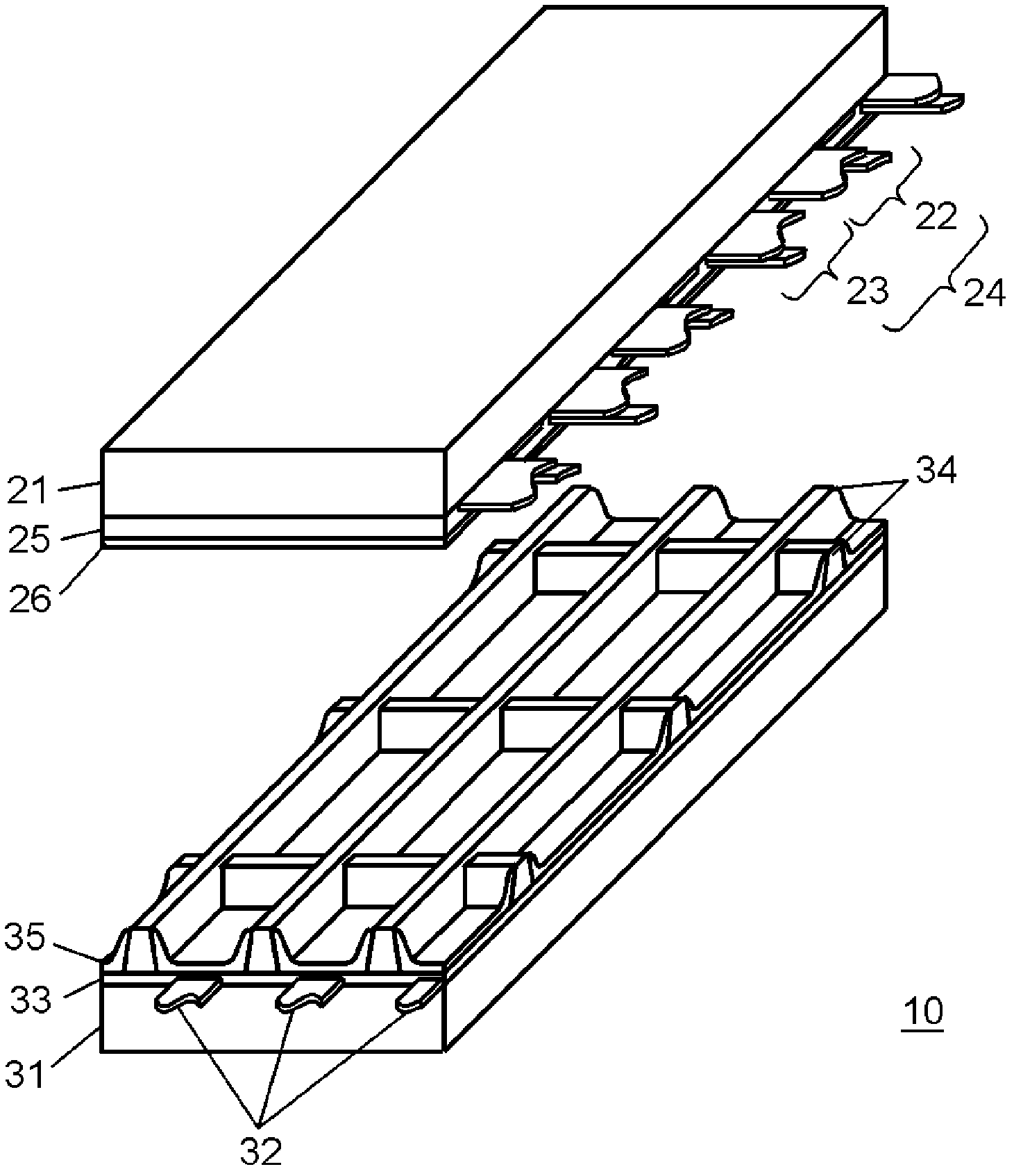
[0032]figure 1 It is an exploded perspective view of panel 10 used in the plasma display device according to Embodiment 1 of the present invention. A plurality of display electrode pairs 24 including scan electrodes 22 and sustain electrodes 23 are formed on front substrate 21 made of glass. Furthermore, a dielectric layer 25 is formed to cover the display electrode pairs 24 , and a protective layer 26 is formed on the dielectric layer 25 . The protective layer 26 is formed of magnesium oxide, which is a material with high electron emission performance, in order to facilitate discharge. A plurality of data electrodes 32 are formed on rear substrate 31 , and dielectric layer 33 is formed so as to cover data electrodes 32 , and grid-shaped barrier ribs 34 are further formed thereon. Phosphor layers 35 that emit light in respective colors of red, green, and blue are provided on the side surfaces of the barrier ribs 34 and the dielectric layer 33 . As a red phosphor, for example...

Embodiment approach 2

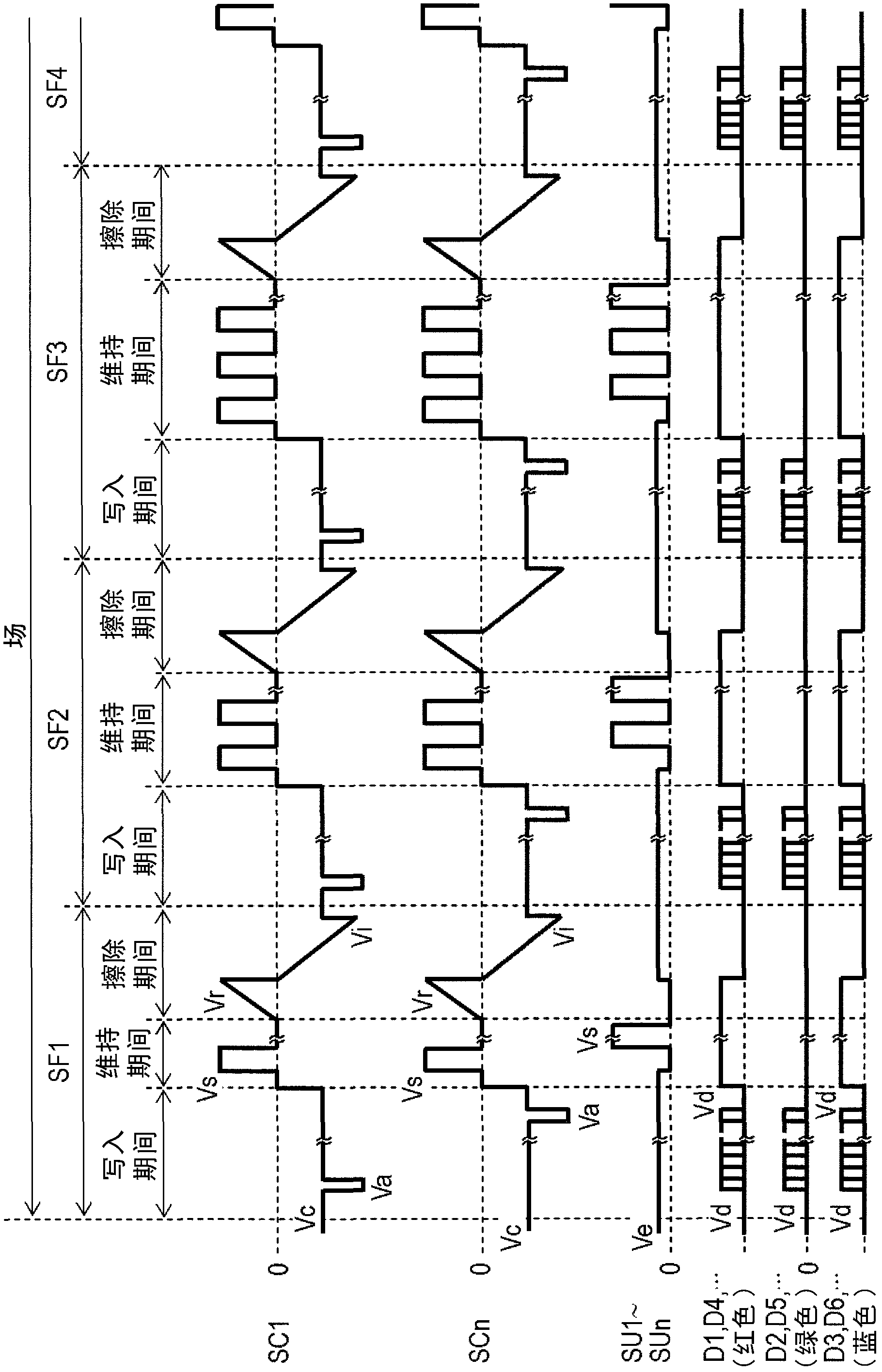
[0099] Hereinafter, other driving voltage waveforms of the present invention will be described using the drawings. Figure 10 as well as Figure 11 It is a driving voltage waveform chart applied to each electrode of the plasma display device in the second embodiment of the present invention, Figure 10 represents the driving voltage waveform in field 1, Figure 11 shows the driving voltage waveform in the second field. Furthermore, in (Embodiment 2), the panel is driven using the first field and the second field alternately. Also in this embodiment, the same subfield configuration as in (Embodiment 1) is used to drive the same panel 10 as in (Embodiment 1).

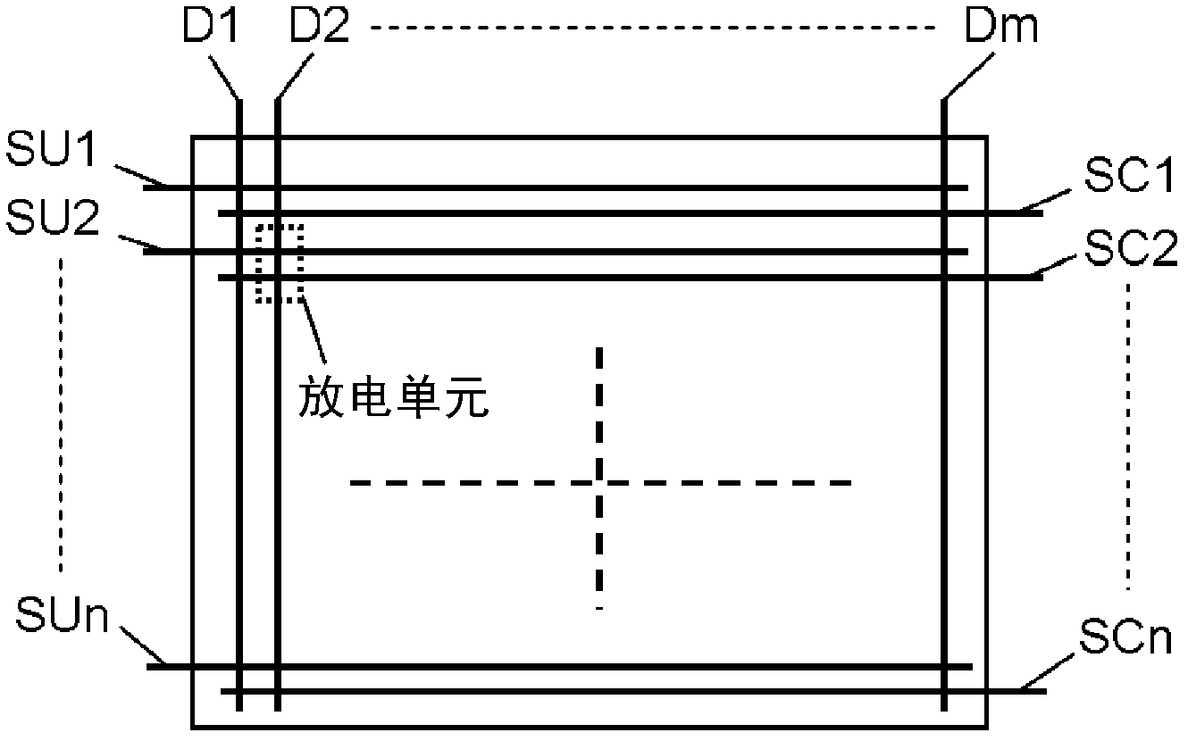
[0100] In the address period of SF1 in the first field, voltage 0 (V) is applied to data electrode D1 through data electrode Dm, voltage Ve is applied to sustain electrode SU1 through sustain electrode SUn, and voltage Vc is applied to scan electrode SC1 through scan electrode SCn. . Next, a scan pulse of voltage Va ...


PUM


Abstract

Disclosed is a plasma display panel drive method, wherein one field is configured using multiple sub-fields having a write-in period during which write-in discharge is caused, a sustain period during which sustain discharge is caused by applying a voltage to the data electrode and by alternately applying a sustain pulse corresponding to the luminance weight to the scan electrode and the sustain electrode, and an erase period during which erase discharge is caused by applying a prescribed voltage to the scan electrode and the sustain electrode, wherein during the erase period, erase discharge is selectively caused only in the discharge cells in which write-in discharge is caused during the immediately previous write-in period, and wherein during the sustain period of at least one sub-field, a voltage lower than the voltage applied to the data electrode of the discharge cell coated with a phosphor emitting red light is applied to the data electrode of the discharge cell coated with a phosphor emitting green light.

Description

technical field [0001] The present invention relates to a driving method of an AC surface discharge plasma display panel and a plasma display device. Background technique [0002] A plasma display panel (hereinafter referred to as "panel") has a plurality of discharge cells having scan electrodes, sustain electrodes, and data electrodes, and excites red, green, and blue colors by using ultraviolet rays generated by gas discharge in the discharge cells. The phosphor emits light to perform color display. [0003] As a method of driving the panel, there is generally a subfield method, that is, a plurality of subfields having an initialization period, a writing period, and a sustaining period are used to form one field, and grayscale display is performed by combining the subfields that emit light. Methods. An initializing operation is performed in an initializing period of each subfield, an addressing operation is performed in an addressing period, and a sustaining operation i...

Claims


Application Information

Patent Timeline
Patent Type & Authority Applications(China)
IPC IPC(8): G09G3/28G09G3/20G09G3/288H04N5/66G09G3/291G09G3/292G09G3/294G09G3/296G09G3/298
CPCG09G3/294G09G3/2965G09G2320/0242G09G3/292
Inventor 吉滨丰
Owner PANASONIC CORP
Why Eureka
Try Eureka