Rotatable machining device

A technology of rotating processing and processing heads, which is applied in metal processing, feeding devices, metal processing equipment, etc., and can solve the problems of failing to give the trachea, trachea winding, winding, etc.

A technology of rotating processing and processing heads, which is applied in metal processing, feeding devices, metal processing equipment, etc., and can solve the problems of failing to give the trachea, trachea winding, winding, etc.

CN102463471AActive Publication Date: 2012-05-23深圳市远望工业自动化设备有限公司

Image

  • Rotatable machining device
  • Rotatable machining device
  • Rotatable machining device

Examples


Embodiment Construction

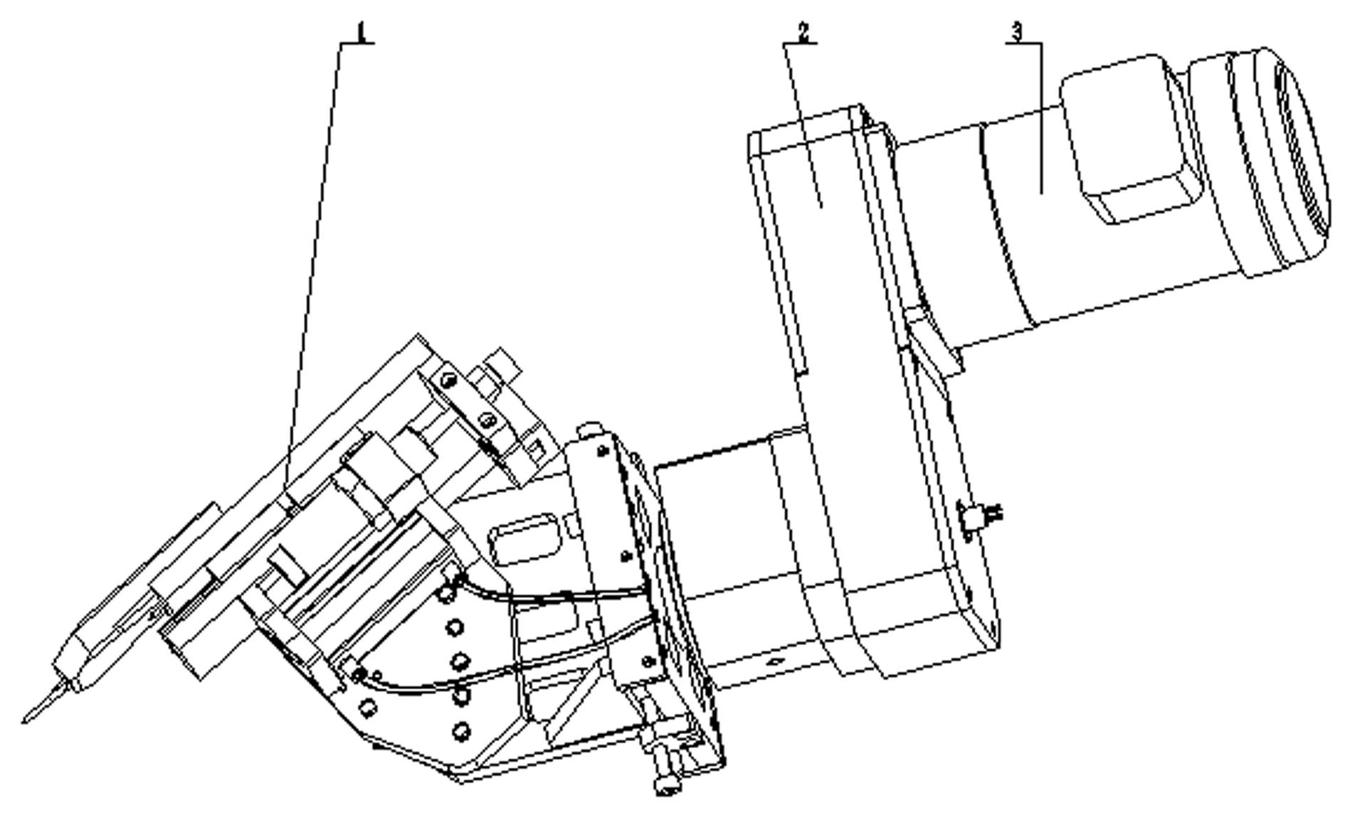
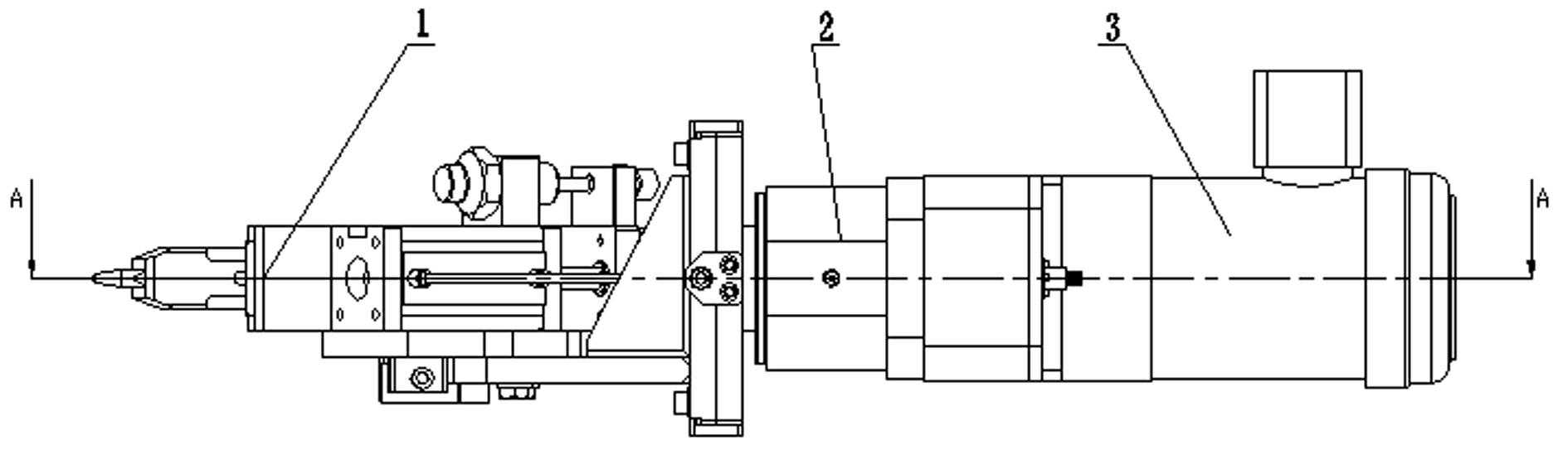
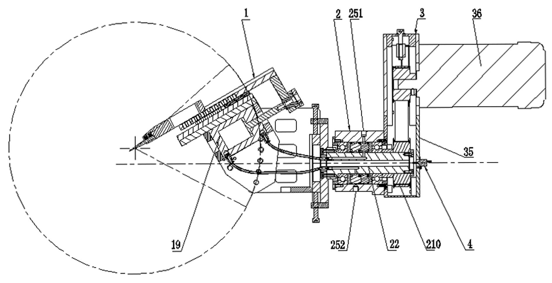
[0029] Such as figure 1 , 2 , 6, 9 (or 10), and 13, the present invention as a whole includes three parts: the processing head 1, the transmission assembly 2 and the rotary power assembly 3 connected in sequence. When the rotary power assembly 3 is working, the rotary power is transmitted to the processing head 1 through the transmission assembly 2, and the processing head 1 starts to perform rotary processing on the workpiece.

[0030] Such as Figure 3 to Figure 5 As shown, the transmission assembly 2 includes a transmission shaft 22, the processing head 1 includes a cylinder 19, and the transmission shaft 22 is provided with an air flow channel A51 and an air flow channel B52. The air cylinder 19 is connected to the airflow channel A51 and the airflow channel B52 through an air pipe A191 and an air pipe B192 respectively.

[0031] Such as Figure 5 As shown, the outer edge of the transmission shaft 22 is provided with a rotating metal sealing sleeve A28 and a rotating m...


PUM


Abstract

The invention discloses a rotatable machining device, which comprises a machining head, a transmission assembly and a rotary power assembly which are connected sequentially, wherein the transmission assembly comprises a transmission shaft; the machining head comprises an air cylinder; an airflow channel is formed on the transmission shaft; and one end of the airflow channel is connected with the air cylinder, and the other end of the airflow channel is communicated with an air source. When the rotatable machining device is used, airflow is conveyed to the air cylinder by the airflow channel or is outputted from the air cylinder; and the transmission shaft and the air cylinder keep static relatively when the transmission shaft rotates, so the problem that an air pipe connected with the airflow channel and the air cylinder is wound due to the rotation of the transmission shaft can be solved.

Description

technical field [0001] The invention relates to a processing device, in particular to a rotatable processing device. Background technique [0002] With the improvement of the degree of automation in the field of machining, the combined motion of the linear reciprocating motion of the cylinder and the rotary motion of the motor has been widely used. The utility model patent with the authorized notification number CN201070762Y disclosed a utility model patent named "Rotary Friction Welding Manipulator" on June 11, 2008. In this patent document, the patentee discloses the following technical solution: the main shaft of the rotary friction welding mechanism has a cylindrical inner chamber, and a sliding rod coaxial with the main shaft and capable of rotating together with the main shaft is arranged in the inner chamber. A tool is provided at the end of the sliding rod, and the tail end of the sliding rod and the main shaft are respectively connected with the air cylinder to rea...

Claims


Application Information

Patent Timeline
23 May 2012
Publication
CN102463471A
IPC
B23Q1/26; B23Q5/00; B23Q5/26
Inventors
龙超祥