
Electrolytic tank structure for preventing upwarp of tank shell during the start-up period of electrolytic tank

An electrolytic cell and cell shell technology, applied in the field of electrolytic cell structure, can solve the problems affecting the service life of the lining, deformation of the lining of the electrolytic cell, uneven distribution of cathode current, etc., so as to solve the uneven distribution of cathode current, improve the service life, The effect of solving inner lining damage

Inactive Publication Date: 2014-09-17
GUIYANG AL-MG DESIGN & RES INST
View PDF6 Cites 0 Cited by
  • Summary
  • Abstract
  • Description
  • Claims
  • Application Information

AI Technical Summary

Problems solved by technology

[0006] The technical problem to be solved by the present invention is to provide an electrolytic cell structure that prevents the cell shell from arching up during the start-up of the electrolyzer, so as to overcome the problem in the prior art that the cathode carbon block of the electrolyzer is arched up, resulting in uneven distribution of cathode current; Deformation of the lining of the electrolytic cell may cause damage to the lining and affect the service life of the lining, etc.

Method used


Image

  • Electrolytic tank structure for preventing upwarp of tank shell during the start-up period of electrolytic tank
  • Electrolytic tank structure for preventing upwarp of tank shell during the start-up period of electrolytic tank
  • Electrolytic tank structure for preventing upwarp of tank shell during the start-up period of electrolytic tank

Examples


Embodiment Construction

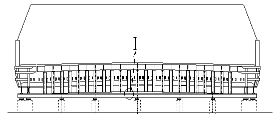
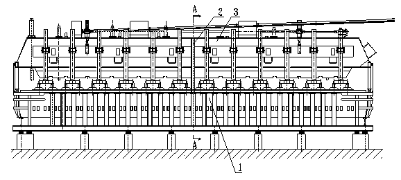
[0019] Embodiment of the present invention: two temporary supports 2 are arranged in the middle of the electrolytic tank and on both sides of the large surface.

[0020] The upper end of the temporary support 2 is pushed against the upper edge of the superstructure girder 3 , and the lower end is pushed against the inner side of the edge of the tank shell 1 .

[0021] Alternatively, the upper end of the temporary support 2 is pushed against the lower edge of the superstructure girder 3 , and the lower end is pushed against the inner side of the edge of the tank shell 1 .

[0022] An insulation board is arranged between the upper end of the temporary support 2 and the upper structural girder 3 , and between the lower end and the tank shell 1 .

[0023] For the case where the upper end of the temporary support 2 is pushed against the upper edge of the superstructure girder 3: the upper end should be pushed against the upper edge of the superstructure girder 3 from the outside to...


PUM


Abstract

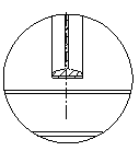
The invention discloses an electrolytic cell structure that prevents the cell shell from arching up during the start-up of the electrolytic cell. Two temporary supports (2) are arranged in the middle of the electrolytic cell and on both sides of the large surface. The upper end of the temporary support (2) is connected with the upper structural beam ( 3) Connection, the lower end is connected with the tank shell (1). The upper end of the temporary support (2) is pushed against the upper edge of the superstructure girder (3), and the lower end is pushed against the inner side of the edge of the tank shell (1); or, the upper end of the temporary support (2) is pushed against the lower edge of the superstructure girder (3), The lower end is pushed against the inner side of the edge of the tank shell (1). Insulating plates are arranged between the upper end of the temporary support (2) and the superstructure girder (3), and between the lower end and the tank shell (1). The present invention adds a temporary support in the middle of the tank shell, so that the weight of the upper structure is pressed against the middle of the tank shell through the temporary support, thereby suppressing the upward arching of the tank shell during the start-up of the electrolytic cell, and solving the problem of the upward arching and electrolysis of the cathode carbon block of the electrolytic cell. The groove lining is deformed, which improves the service life of the lining.

Description

technical field [0001] The invention relates to a novel electrolyzer structure. Background technique [0002] During the start-up of the aluminum electrolytic cell, there will be a shell arching phenomenon, which will affect the normal production of the electrolytic cell (refer to "Light Metals" 2005, No. 4, p31, the paper "The shell arching during the start-up of the electrolytic cell", Wang Yu). The aluminum electrolytic cell needs to melt the cryolite electrolyte at the initial stage of start-up, and the entire tank chamber is filled with molten electrolyte at ~1000°C, and the lava is tumbling, which is the period when the temperature in the tank chamber is the highest. At this time, the furnace side of the tank has not yet formed, and there is no effective heat insulation layer of side crust around the electrolytic tank. The tank shell of the electrolytic tank has to withstand the highest temperature during this period. . [0003] The tank shells of the electrolytic ce...

Claims


Application Information

Patent Timeline
Patent Type & Authority Patents(China)
IPC IPC(8): C25C3/08
Inventor 王愚
Owner GUIYANG AL-MG DESIGN & RES INST
Learn More