
spinning machinery

A mechanical and open-end spinning technology, applied to spinning machines, open-end spinning machines, continuous winding spinning machines, etc., can solve the problem of too little and achieve the effect of improving the quality of spun yarn

Active Publication Date: 2016-06-01
MURATA MASCH LTD
View PDF7 Cites 0 Cited by
  • Summary
  • Abstract
  • Description
  • Claims
  • Application Information

AI Technical Summary

Problems solved by technology

[0003] The air spinning device has a problem that, for example, when a spun yarn is produced from a fiber bundle to which an oil is applied, such as polyester fiber, the oil adheres to and accumulates on the wall surface of the spinning chamber.
Therefore, depending on the number of worktables of the air spinning device, the supply amount of the anti-blocking agent may become too much or too little.

Method used


Image

  • spinning machinery
  • spinning machinery
  • spinning machinery

Examples


Embodiment Construction

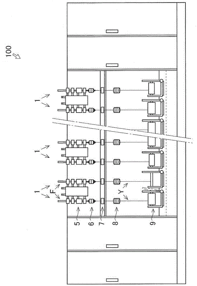
[0035] use figure 1 The spinning machine 100 according to the embodiment of the present invention will be described. Such as figure 1 As shown, the spinning machine 100 is mainly composed of a plurality of spinning units 1 . The spinning machine 100 is equipped with an air distribution device 2 ( figure 1 Not shown in the figure, refer to Figure 7 ) and an additive supply device 3 ( figure 1 Not shown in the figure, refer to Figure 7 ).

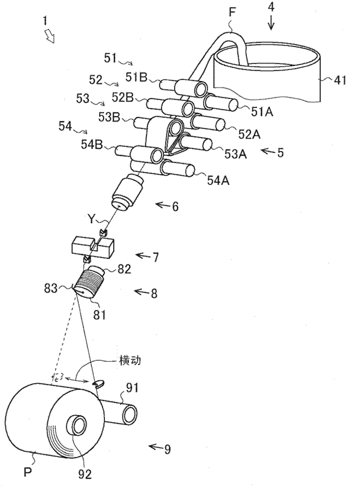
[0036] First, use figure 2 The configuration of the spinning unit 1 will be described in detail.

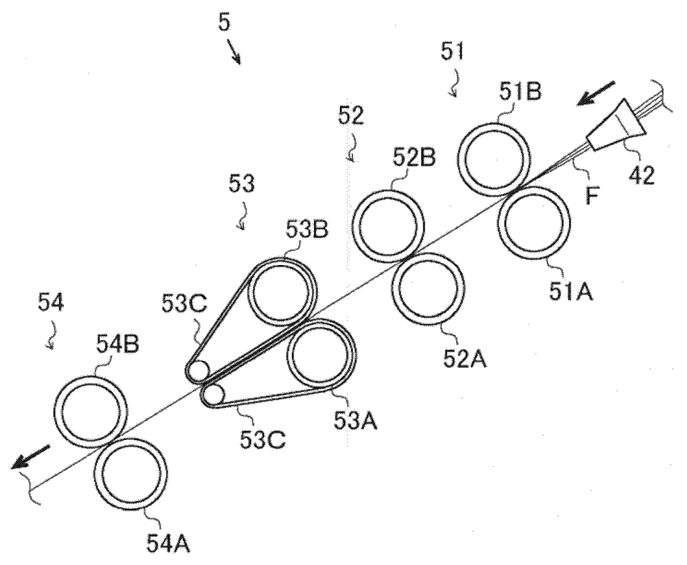
[0037] The spinning unit 1 is a spinning machine for producing a spun yarn Y from a fiber bundle (hereinafter referred to as "sliver") F to produce a package P. The spinning unit 1 includes a sliver supplying unit 4, a draft device 5, an air-jet spinning device 6, and A yarn defect detection device (yarn defect detecting device) 7, a tension stabilizing device (tension stabilizing device) 8 and a winding device (winding device) 9.

...


PUM


Abstract

A spinning machine (100) is provided with a plurality of spinning units (1), each of which has an air-jet spinning device (6) that twists a fiber bundle F using a whirling airflow. The spinning machine (100) includes an air transporting device (21) that transports air, an air pipe (22) that guides the air transported by the air transporting device (21), an additive supplying device (3) that supplies an additive to the air pipe (22) at upstream of a branch where the air flowing through the air pipe (22) branches off towards the air-jet spinning devices (6), and a control device (C) that adjusts the volume of an additive to be supplied by the additive supplying device (3).

Description

technical field [0001] The present invention relates to a technology of a spinning machine (Spinning Machine) equipped with a plurality of spinning units. Background technique [0002] Conventionally, there is known an air spinning device that twists a fiber bundle with a whirling airflow of air to produce a spun yarn. The air spinning device produces a spun yarn by supplying air to a spinning chamber to generate a whirling airflow so that the fibers constituting the fiber bundle are twisted (for example, JP 2009-1935 A) . [0003] The air spinning device has a problem that, for example, when a spun yarn is produced from a fiber bundle to which an oil is applied, such as polyester fiber, the oil adheres to and accumulates on the wall surface of the spinning chamber. Therefore, a technique has been proposed that prevents the accumulation of the oil agent by adding an anti-deposition agent to the air supplied to the air spinning device (for example, JP-A-2008-95208). [000...

Claims


Application Information

Patent Timeline
Patent Type & Authority Patents(China)
IPC IPC(8): D01H4/02
CPCD01H1/115
Inventor 太田成利坂元直孝
Owner MURATA MASCH LTD
Learn More