

Fuel injection valve
A fuel injection valve and fuel technology, applied in the direction of fuel injection devices, charging systems, engine components, etc., can solve the problems of fuel flow rate reduction, guide fuel, etc., to achieve the effect of suppressing flow rate reduction and realizing atomization
- Summary
- Abstract
- Description
- Claims
- Application Information
AI Technical Summary
Problems solved by technology
Method used
Image

Examples
Embodiment 1
[0033] The fuel injection valve 1 of the first embodiment will be described.
[0034] [Structure of Fuel Injection Valve]
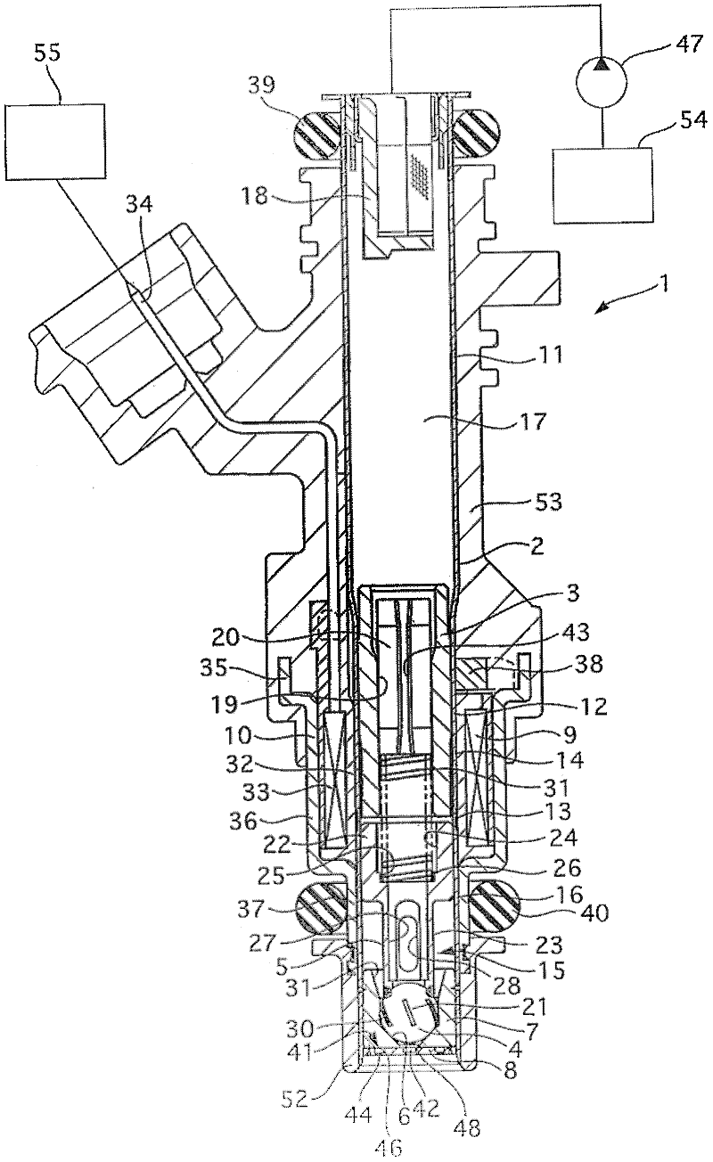
[0035] figure 1 is an axial sectional view of the fuel injection valve 1 . This fuel injection valve 1 is used in an automobile engine and the like.
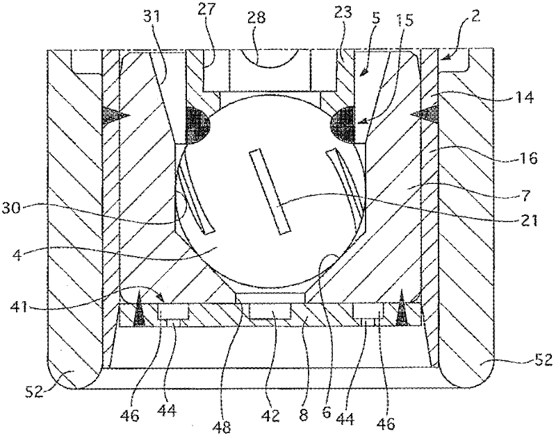
[0036] The fuel injection valve 1 has: a magnetic cylinder body 2, a core cylinder body 3 accommodated in the magnetic cylinder body 2, a valve body 4 slidable in the axial direction, a valve shaft 5 integrally formed with the valve body 4, and a The valve seat part 7 of the valve seat 6 that is closed by the valve body 4, the nozzle plate 8 with the injection hole that injects fuel when the valve is opened, the electromagnetic coil 9 that makes the valve body 4 slide in the valve opening direction when the valve is energized, and the yoke 10 that induces magnetic flux .
[0037] The magnetic cylinder 2 is made of, for example, a metal pipe formed of a magnetic metal material such as electromagnetic sta...
Embodiment 2
[0075] The fuel injection valve 1 of the second embodiment will be described. In the fuel injection valve 1 of the first embodiment, the radially outer side wall 45 a is formed on the tangent line of the central chamber 42 with respect to the central chamber 42 of the communicating passage 45 . With this structure, in the fuel injection valve 1 of the second embodiment, a stepped portion 45c is formed at the connecting portion between the side wall 45a of the communication passage 45 and the central chamber 42 .
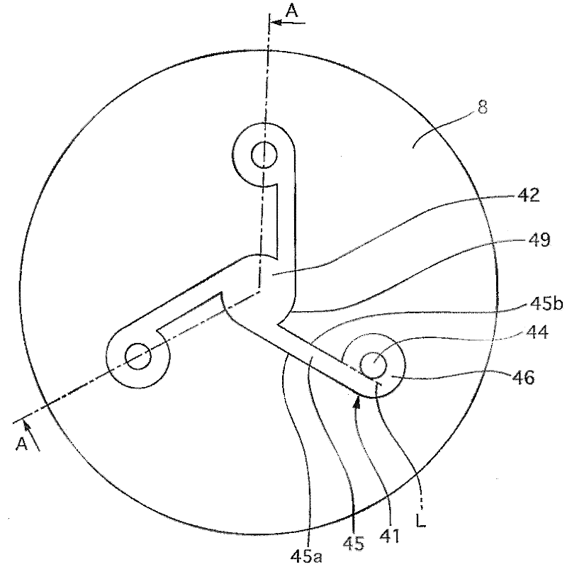
[0076] Figure 6 It is a plan view of the nozzle plate 8 viewed from one end side in the axial direction and a diagram showing the flow of fuel. Figure 6 (a) represents the whole nozzle plate, Figure 6 (b) is Figure 6 (a) An enlarged view of a portion indicated by a dotted line circle B.
[0077] Figure 6 As shown, a stepped portion 45c is formed at the connecting portion between the side wall 45a of the communication path 45 and the central chamber 42 . Th...
Embodiment 3
[0084] The fuel injection valve 1 of the third embodiment will be described. The fuel injection valve 1 of the first embodiment is formed such that the width of the communication passage 45 is constant when viewed from one end side in the axial direction. With this configuration, in the fuel injection valve 1 according to the third embodiment, the width viewed from one end side in the axial direction is formed such that the communication passage 45 narrows toward the swirl imparting chamber 46 .
[0085] Figure 7 It is a plan view of the nozzle plate 8 viewed from one end side in the axial direction and a diagram showing the flow of fuel. Such as Figure 7 As shown, with respect to the central chamber 42 of the communication passage 45, the radially inner side wall 45b is formed as follows, that is, the radially outer side wall 45a is inclined relative to the central chamber 42, and the swirl imparting chamber 46 is relatively The central chamber 42 is close to the radiall...
PUM
 Abstract
Description
Claims
Application Information