Multi-stage centrifugal pump with improved impeller arrangement

A centrifugal pump and impeller technology, which is applied to the components, pumps, pump elements, etc. of the pumping device for elastic fluid, which can solve the problem of unfavorable versatility, the cutting capacity of a single impeller is not enough to meet the adjustment needs, and the head difference is large. and other problems, to achieve the effect of reducing one-time investment, reducing product models, and expanding performance range

Inactive Publication Date: 2012-05-23
上海福思特流体机械有限公司
View PDF4 Cites 3 Cited by
  • Summary
  • Abstract
  • Description
  • Claims
  • Application Information

AI Technical Summary

Problems solved by technology

[0005] (1) Multi-stage pumps generally have a large head, so the head of a single-stage impeller is also high, so the head difference between adjacent stages of pumps is relatively large. In order to cover a wider performance range, more types of pumps need to be designed , which is not conducive to generality;
[0006] (2) In the case of changes in some working conditions, such as mines extending downwards, the head requirements of the pump will gradually increase. If this condition is to be met, the pump should reserve space for increasing the impeller when leaving the factory, and the single-stage impeller The head is too large to meet the needs of the working conditions as much as possible;
[0007] (3) Since the impeller and guide vane of the multi-stage pump are designed in pairs, if the impeller needs to be cut to meet the requirements of the working conditions, the cutting volume of a single impeller is not enough to meet the adjustment needs of the multi-stage pump under high head, and the lowered Head is distributed to all impellers, which results in high workload and reduced pump efficiency

Method used


Image

  • Multi-stage centrifugal pump with improved impeller arrangement
  • Multi-stage centrifugal pump with improved impeller arrangement

Examples


Embodiment

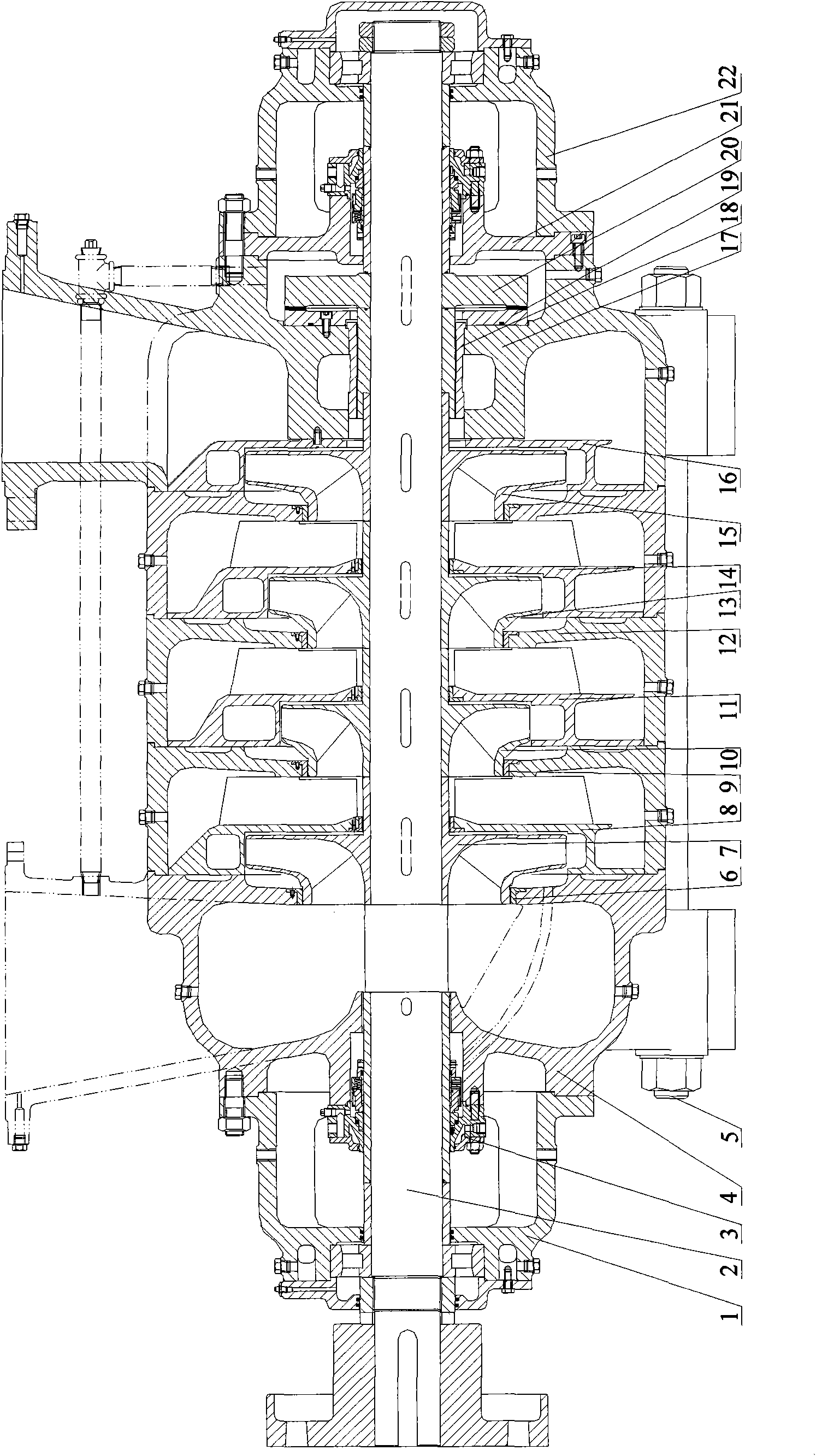
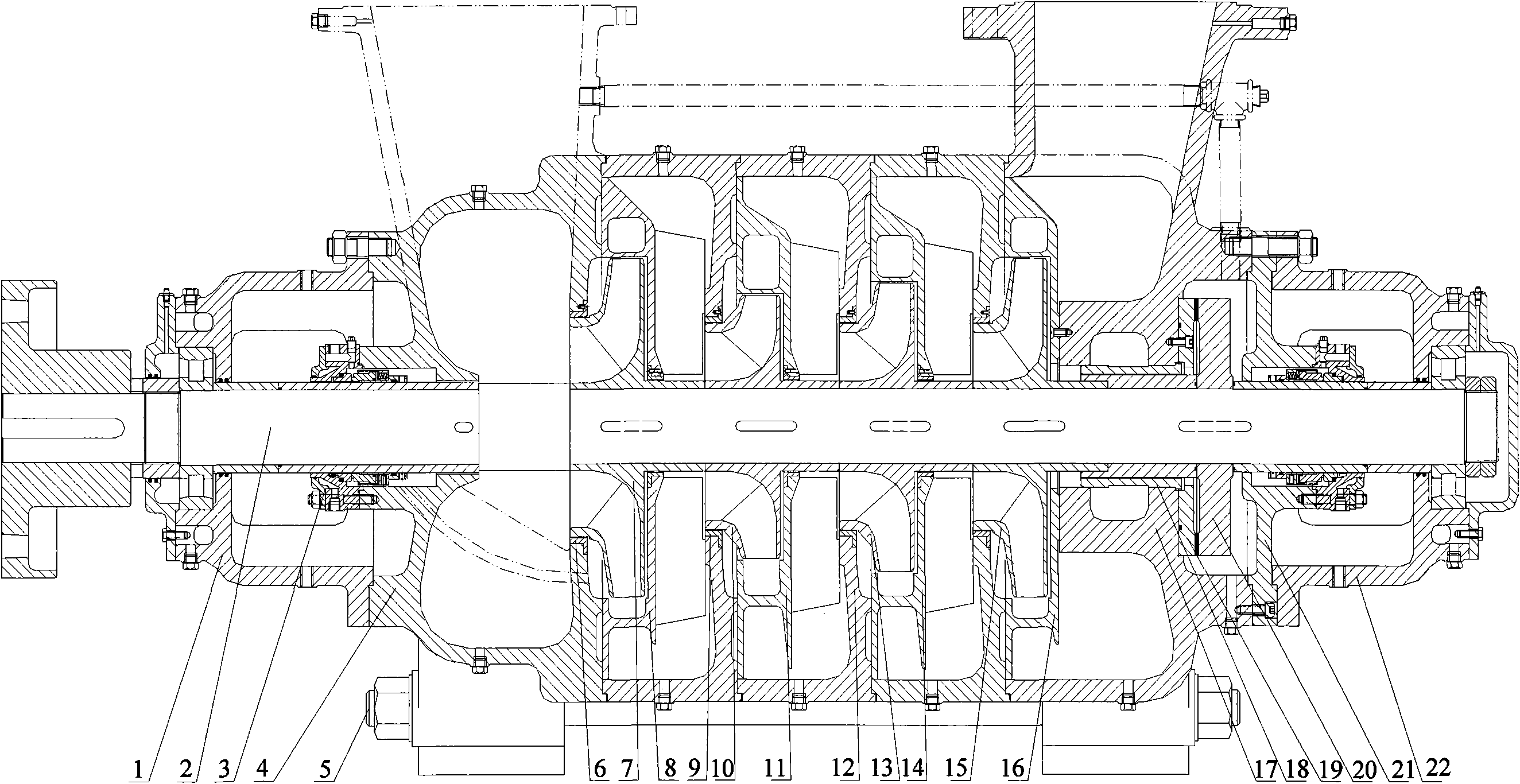
[0023] A multi-stage centrifugal pump with improved impeller arrangement, its structure is as follows figure 1 As shown, the centrifugal pump includes left bearing part 1, shaft 2, mechanical seal part 3, water inlet section 4, tension bolt 5, inlet seal ring 6, primary impeller 7, guide vane 8, secondary seal ring 9, 1 / 2 stage impeller 10, 1 / 2 stage guide vane 11, middle section 12, 2 / 3 stage impeller 13, 2 / 3 stage guide vane 14, interstage impeller 15, final stage guide vane 16, water outlet section 17, throttling Sleeve 18, balance ring 19, balance plate 20, tail cover 21, right bearing part 22, left bearing part 1 and right bearing part 22 are arranged on the left and right sides of shaft 2 of the centrifugal pump, water inlet section 4, first stage impeller 7 , guide vane 8, 1 / 2 stage impeller 10, 1 / 2 stage guide vane 11, middle section 12, 2 / 3 stage impeller 13, 2 / 3 stage guide vane 14, interstage impeller 15, final stage guide vane 16, water outlet Section 17, throttli...


PUM


Abstract

The invention relates to a multi-stage centrifugal pump with improved impeller arrangement. The centrifugal pump comprises impellers sheathed on a shaft of the centrifugal pump, wherein the impellers comprise a first-stage impeller, a 1/2-stage impeller, a 2/3-stage impeller and an inter-stage impeller, and the first-stage impeller, the 1/2-stage impeller, the 2/3-stage impeller and the inter-stage impeller are sequentially connected in series and are sheathed on the shaft of the centrifugal pump. Compared with the prior art, the multi-stage centrifugal pump has the advantages that the performance range of the single-type pump is greatly expanded, the product types are reduced, the universality is enhanced, the pump performance is similar to the actual work condition, the pump can operate in efficient regions, energy sources are saved, in addition, the one-time investment under the complicated work condition is reduced, and the adjustability of the product performance is enhanced.

Description

technical field [0001] The invention relates to a multistage centrifugal pump, in particular to a multistage centrifugal pump with improved impeller arrangement. Background technique [0002] The segmented multi-stage centrifugal pump adopts the form of radial split and multiple impellers connected in series. Its main parts are: water inlet section, middle section, water outlet section, shaft, impeller, guide vane, sealing ring, balance disc, balance ring, bearing parts, tension bolts, etc. The head of this pump depends on the number of stages of the pump, so this pump has a wide range of heads, and the head it can achieve is the highest among centrifugal pumps. [0003] The general arrangement of impellers in existing multi-stage centrifugal pumps is to use a first-stage impeller and multiple inter-stage impellers in series. The head of the impeller between the stages is the head difference between the pumps of different stages. [0004] This arrangement is applicable in...

Claims


Application Information

Patent Timeline
Patent Type & Authority Applications(China)
IPC IPC(8): F04D1/06F04D29/22
Inventor 童弘寿满光张浩
Owner 上海福思特流体机械有限公司
Why Eureka
Try Eureka