
Air-conditioning system and control method of condensation fan thereof

A technology for condensing fans and air-conditioning systems, which is applied in the direction of control input related to system state, control input related to air characteristics, space heating and ventilation control input, etc. It can solve the problems of single control mode and low efficiency of air-conditioning system, etc. achieve efficient operation

Active Publication Date: 2012-05-23
VERTIV CORP
View PDF6 Cites 62 Cited by
  • Summary
  • Abstract
  • Description
  • Claims
  • Application Information

AI Technical Summary

Problems solved by technology

[0004] The technical problem to be solved by the present invention is to provide a control method for the condensing fan of the air-conditioning system, aiming at the defects of the prior art that the control mode of the condensing fan of the air-conditioning system is single, which leads to low efficiency of the air-conditioning system. When one control mode fails, it will automatically switch to other control modes to ensure the normal and efficient operation of the air conditioning system

Method used


Image

  • Air-conditioning system and control method of condensation fan thereof
  • Air-conditioning system and control method of condensation fan thereof
  • Air-conditioning system and control method of condensation fan thereof

Examples


Embodiment Construction

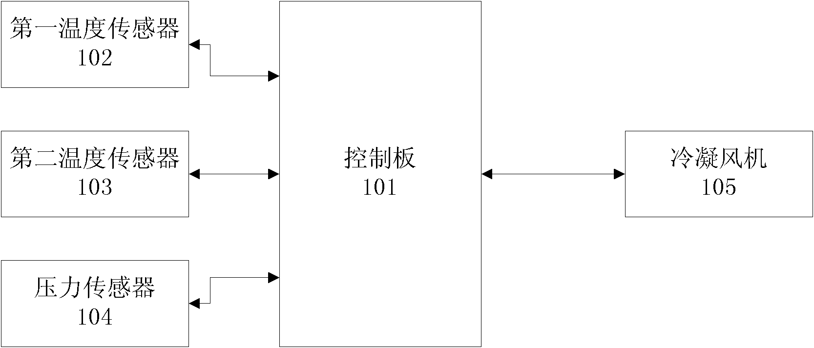
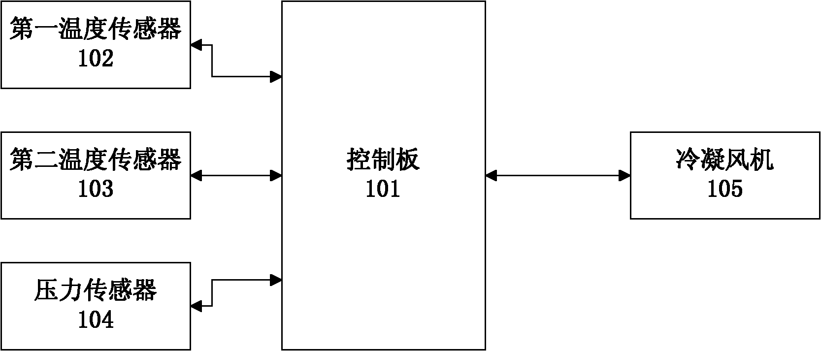
[0037] Such as figure 1 As shown, in the logic diagram of Embodiment 1 of the outdoor unit of the air conditioning system of the present invention, the outdoor unit includes a condenser (not shown), a control board 101, a first temperature sensor 102, a second temperature sensor 103, a pressure sensor 104 and Condensing fan 105. Wherein, the pressure sensor 104 can be arranged at the inlet of the condenser to collect the inlet pressure of the condenser, and can also be arranged at the outlet of the condenser to collect the outlet pressure of the condenser; the first temperature sensor 102 is arranged at the condenser The outer wall of the condenser is used to collect the ambient temperature; the second temperature sensor 103 is arranged at the outlet of the condenser and wrapped with thermal insulation cotton so as to effectively prevent the heat exchange between the condenser outlet pipe wall and the outside air. The second temperature sensor 103 is used To collect the conde...


PUM


Abstract

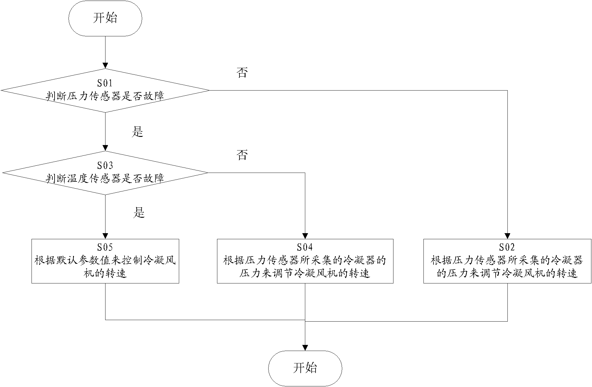
The invention relates to an air-conditioning system which comprises an indoor machine and an outdoor machine, wherein the outdoor machine comprises a condenser, a condensation fan, a temperature sensor, a pressure sensor and a control panel, wherein the temperature sensor is used for collecting temperature; the pressure sensor is used for collecting condensation pressure; the control panel is used for detecting whether the pressure sensor and / or the temperature sensor malfunction / malfunctions, regulating the rotation speed of the condensation fan according to the condensation pressure collected by the pressure sensor when the pressure sensor does not malfunction, regulating the rotation speed of the condensation fan according to the temperature collected by the temperature sensor when the pressure sensor malfunctions but the temperature sensor does not malfunction, and controlling the rotation speed of the condensation fan according to default parameter values when both the pressure sensor and the temperature sensor malfunction. Through implementing the technical scheme provided by the invention, the control method can be automatically switched when a single control method is invalid, and the normal and efficient operation of the air-conditioning system can be ensured.

Description

technical field [0001] The invention relates to refrigeration technology, more specifically, to an air-conditioning system and a control method for a condensing fan thereof. Background technique [0002] With the rapid development of science and technology and the continuous innovation and improvement of technology, people have higher and higher requirements for the reliable and efficient operation of air conditioning systems. The intelligence of the air conditioning system has become the highlight of technological innovation and is gradually being paid attention to by people. At the same time, with the national call for energy conservation and emission reduction, the air conditioning system has higher and higher requirements for energy conservation. An air conditioning system usually consists of the following parts, including compressor, evaporator, throttling device, condenser and control system. In the refrigeration industry, we will reduce energy consumption and improv...

Claims


Application Information

Patent Timeline
IPC IPC(8): F24F11/02F24F11/00
CPCF24F11/0079F24F2011/0041Y02B30/743F24F2011/0052F25B2600/111F24F11/0012F24F11/02F24F11/00Y02B30/746F24F11/30F24F2110/10F24F2110/40F24F11/32F24F11/77Y02B30/70F24F11/871F24F11/46F24F11/63F24F11/86F24F11/38F24F2140/00
Inventor 李建平王林王政余先耀张宏宇约翰·乔治史蒂夫·赛拉林万来吕宗涛
Owner VERTIV CORP
Learn More