
Stiffness test bench device of debugging engine hood and use method thereof

A technology of test bench and engine cover, which is applied in the field of vehicle testing to achieve the effect of simple operation and strong applicability

Active Publication Date: 2012-05-23
ZHEJIANG GEELY AUTOMOBILE RES INST CO LTD +1
View PDF9 Cites 27 Cited by
  • Summary
  • Abstract
  • Description
  • Claims
  • Application Information

AI Technical Summary

Problems solved by technology

[0008] The invention solves the problem that the existing auto parts collision test machine is not suitable for completing the collision test of the engine hood, provides an adjustable engine hood stiffness test bench device and its use method, and completes the collision of the engine hood in a targeted manner test

Method used


Image

  • Stiffness test bench device of debugging engine hood and use method thereof
  • Stiffness test bench device of debugging engine hood and use method thereof
  • Stiffness test bench device of debugging engine hood and use method thereof

Examples


Embodiment 1

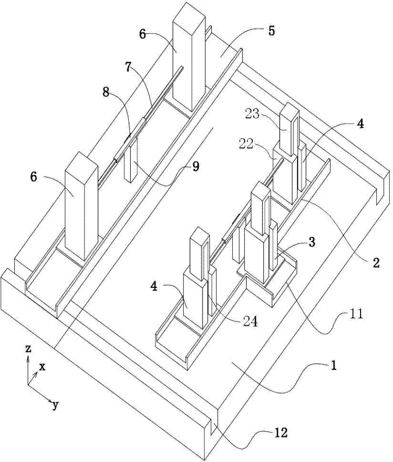
[0033] Embodiment 1: A kind of adjustable hood stiffness test bench device (see attached figure 1 ), including a platform base 1, rectangular concave base guide rails 12 are arranged on both sides of the platform base, and fixed guide rails 2 and movable guide rails are arranged on the platform base in a direction perpendicular to the base guide rails 5. The fixed guide rail is parallel to the movable guide rail, the fixed guide rail is fixed to the base of the bench, the two ends of the movable guide rail straddle the base guide rail, and a lead screw 20 is placed in the base guide rail, and the two ends of the lead screw pass through the bearing 18 is fixed on the base guide rail, the end of the lead screw is connected with a stepping motor 21, the lower surface of the two ends of the movable guide rail is fixed with a lead screw nut 19, the position of the lead screw nut is aligned with the base guide rail, and the lead screw penetrates into the wire inside the lever nut (s...

Embodiment 2

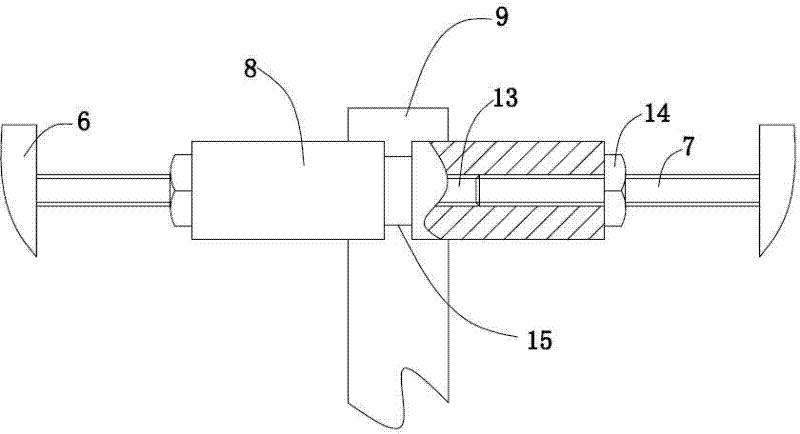
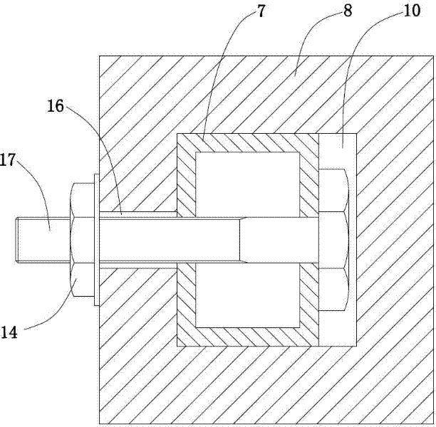
[0038] Embodiment 2: A kind of adjustable hood rigidity test bench device (see attached figure 1 ), the hood hinge connection column and the buffer block connection column are respectively provided with a sleeve fixing bracket and a support rod. The sleeve and the bracket in the sleeve fixing bracket are fixedly connected, and a square through hole 10 is arranged in the sleeve. The side wall midline position of sleeve is provided with slot 16, and support bar is the square bar that matches with through hole, and the end of support bar is fixed with locking screw 17, and the end of locking screw stretches in the slot, locks Lock nut 14 is screwed on the tightening screw, and lock nut tightens and fixes the support rod. Refer to Example 1 for all the other structures.

[0039] A method for using an adjustable engine hood stiffness test bench device, comprising the following steps: (1) measuring the X-direction distance between the two left and right hood hinges of the engine ho...


PUM


Abstract

The invention relates to a stiffness test bench device of debugging engine hood used in the automobile collision test and use method thereof, which solves the problem that the traditional automobile part collision tester is not suitable for finishing the collision test of the engine hood; a hood lock connection column and a hood hinge connection column are arranged on the base of the bench; the hood hinge connection column is in the fixed height; a T-shaped fixing guide rail is fixed on the base of the bench; a buffer block connection column moving along the fixing guide rail is arranged on the fixing guide rail; a movable guide rail is arranged on the base of the bench; the hood hinge connection column is movably arranged on the movable guide rail; and the buffer block connection column and the hood lock connection column are in the structure with variable height. The installation angle of the engine hood in the normal state is simulated via the hood hinge connection column, the buffer block connection column and the hood lock connection column; the tested results are in accordance with the actual situations; the stiffness of the engine hood is really reflected; and the stiffness test bench device of debugging engine hood is applicable for the engine hoods in the different automobile types.

Description

technical field [0001] The invention belongs to the field of vehicle testing, in particular to an adjustable engine hood rigidity test stand device used in a vehicle collision test and a method for using the same. Background technique [0002] In order to improve the safety performance of automobiles, the automobile crash test is an indispensable means of verification, because most of the accidents are collisions, and the test results basically reflect the safety degree of the automobile to the occupants and pedestrians. The European New Car Safety Evaluation Association's crash test has two basic items, namely frontal and side impact. China's C-NCAP vehicle crash test includes frontal collision, side collision and rear collision. Currently, China only adopts 100% frontal full-contact collision test. [0003] In the collision test between a car and a structure, it is necessary to accelerate the car to the set speed and make it collide with the structure. Because the car cra...

Claims


Application Information

Patent Timeline
IPC IPC(8): G01M7/08
Inventor 吴佳吕铖玮吕晓江王纯刘卫国吴成明赵福全
Owner ZHEJIANG GEELY AUTOMOBILE RES INST CO LTD
Learn More