
Moving device for vacuum absorption

A vacuum adsorption and moving device technology, applied in the direction of transportation and packaging, load hanging components, etc., can solve the problems of air pressure pipe connection damage, maintenance cost increase, time-consuming and other problems, so as to improve safety and provide performance , Improve the effect of aesthetics

Inactive Publication Date: 2012-05-23
SANMEI
View PDF8 Cites 10 Cited by
  • Summary
  • Abstract
  • Description
  • Claims
  • Application Information

AI Technical Summary

Problems solved by technology

[0013] However, although the air pressure tube is accommodated inside the lifting cylinder 90 and rotated by the rotating parts to prevent the air pressure tube from being damaged and to allow it to rotate freely, the function of the vacuum suction moving device infinitely repeats the rotation operation, Causes frequent damage to the connection of the air pressure pipe
[0014] That is, when the straight pipe type air pressure pipe 95 or the coil type air pressure pipe 95 that is installed in the lift shaft 91 or the lift cylinder 90 are damaged, it is necessary to disassemble all of the above lift cylinder 90 to replace the damaged parts. A lot of time is consumed when repairing faults or replacing aging parts
[0015] In particular, when the straight pipe type air pressure pipe 95 inserted into the lifting shaft 91 is damaged, the lifting shaft 91 needs to be disassembled according to its structure, and professional technicians are required. When the pipe is damaged, all lifting cylinders need to be replaced 90

Method used


Image

  • Moving device for vacuum absorption
  • Moving device for vacuum absorption
  • Moving device for vacuum absorption

Examples


Embodiment Construction

[0037] Next, the vacuum adsorption moving device of the present invention will be described in detail in conjunction with the accompanying drawings. When assigning symbols to the above-mentioned drawings, the same symbols are used as much as possible even if they are in different drawings for the same structure, and the disclosed functions and structures that may cause confusion in the description of the present invention are hereby omitted. No longer.

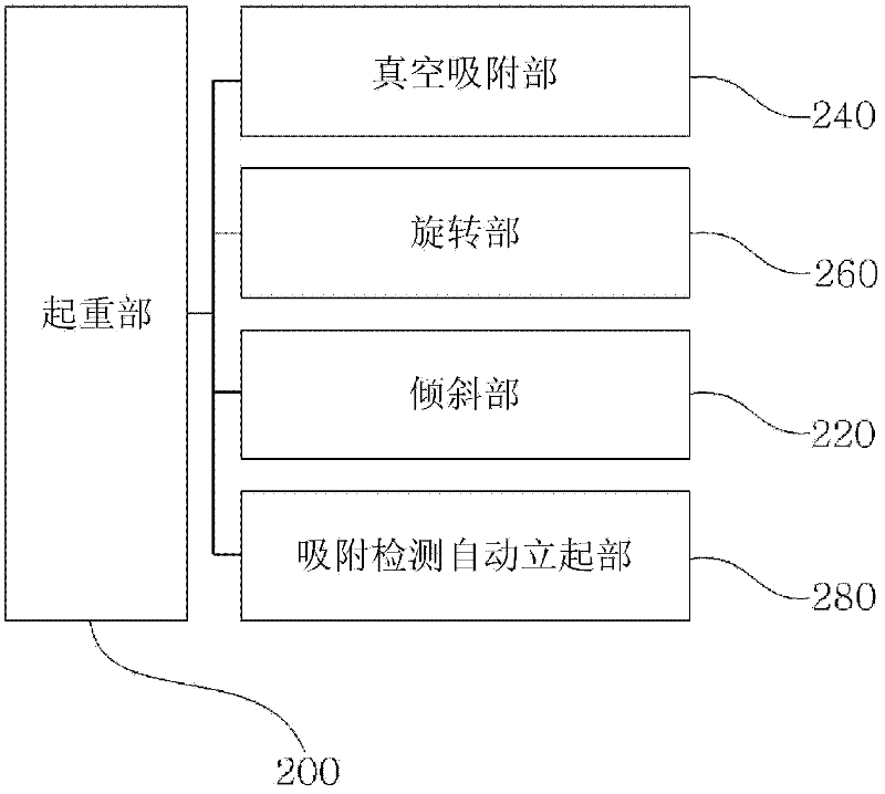
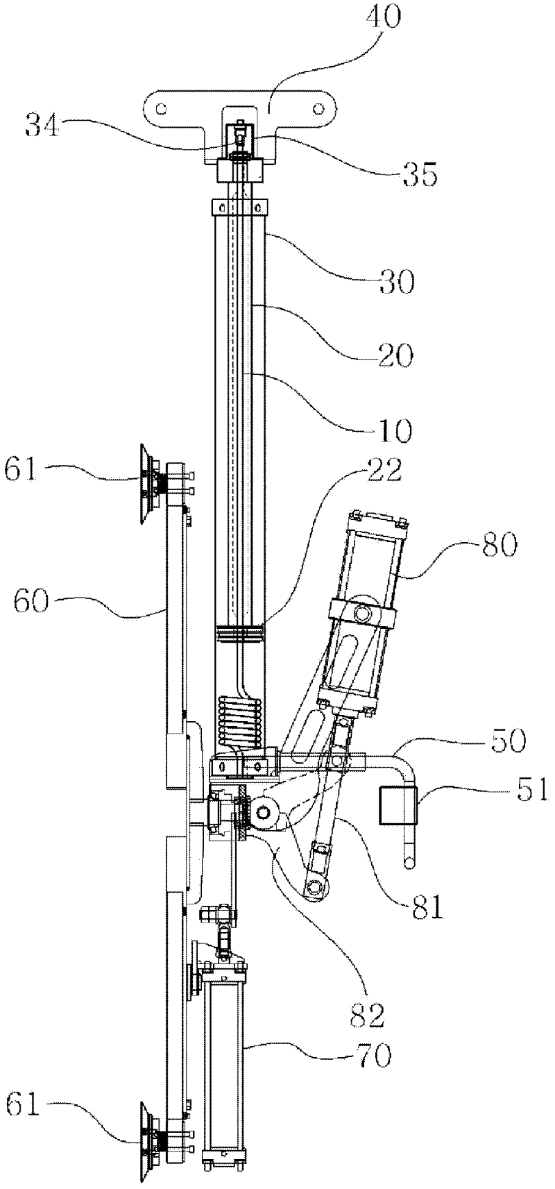
[0038] figure 1 It is a conceptual structural diagram of the vacuum adsorption moving device of the present invention; figure 2 It is a schematic longitudinal structure diagram of a vacuum adsorption moving device according to an embodiment of the present invention; Figure 3a and Figure 3b It is a schematic structural diagram of the lifting cylinder in the vacuum adsorption mobile device according to an embodiment of the present invention; Figure 4 It is a schematic diagram of the operation part of the vacuum adsorpti...


PUM


Abstract

The present invention relates to a moving device for vacuum absorption, wherein: the invention is operated smoothly for equipment functions of which is infinitely and repeatedly rotated in order to move a product such as a large-scale plate glass or a board or the like; and a pneumatic hose is replaced in a very easy and fast manner when the hose has to be replaced due to damage or a worn-out state, thereby largely improving performance of the equipment. The moving device for vacuum absorption of the present invention comprises: a lifting unit (200) which performs an air balancing function; a vacuum absorption unit (220) which is configured to vacuously absorb a transferred object; and a tilting unit (260) which is configured to slopingly drive said vacuum absorption unit (220), wherein: said lifting unit (200) includes a lift cylinder (30); said lift cylinder (30) includes a lifting shaft (20), a lifting piston (22), and an embedded pneumatic hose (10); said embedded pneumatic hose (10) has, in an integrated shape, a straight pipe unit (12) positioned on a straight line and a coil-shaped coil unit (11) which is increased or compressed by being succeeded with said straight pipe unit (12); a lower end of the coil unit (11) is exposed to the outside through a penetration hole (37) vertically pierced on a lower end cap (36) of the lift cylinder (30), so that the lower end is connected with a pneumatic circuit unit; and an upper end of the straight pipe unit (12) is exposed to an upper end of the lifting shaft (20) through a penetration hole of the lifting piston (22) and a shaft hollow portion (21) of the lifting shaft (20), so that the upper end is combined with a rotary joint (34) and is connected to an external vacuum motor.

Description

technical field [0001] The present invention relates to a vacuum suction moving device, and more particularly to a vacuum suction moving device which, while functioning as a device for infinitely repeating rotation for the movement of products such as large flat glass or plates, needs to be replaced due to breakage or aging of the air pressure The air pressure tube can also be replaced easily and quickly when the tube is installed, thereby greatly improving the performance of the equipment. Background technique [0002] In general, a vacuum suction moving device is a device that moves or loads a large flat glass or plate according to a work process, and operates while being suspended from a hook of a crane or a lifting device. The vacuum adsorption mobile device includes: an adsorption part frame, equipped with a hook part; a plurality of vacuum adsorption plates, installed on one side of the adsorption part frame; a vacuum motor and a vacuum tank, installed on the other sid...

Claims


Application Information

Patent Timeline
IPC IPC(8): B66C1/02B66C1/10
CPCB66C1/0243
Inventor 崔吉雄
Owner SANMEI
Learn More