Remotely controllable variable flow control configuration and method

A remote control and construction technology, applied in the direction of fluid extraction, earthwork drilling, borehole/well valve device, etc., can solve problems such as expensive, failure to correct characteristics, loss of injected fluid, etc.

Active Publication Date: 2012-05-23
BAKER HUGHES INC
View PDF8 Cites 1 Cited by
  • Summary
  • Abstract
  • Description
  • Claims
  • Application Information

AI Technical Summary

Problems solved by technology

These devices work well for their intended purpose, but they are fixed tools that must be positioned in the completion at the time of construction and replacement requires removal of the completion
It is familiar to those skilled in the art that this operation is expensive
However, correcting property failures is also costly, as for interdigitated production wells, undesired fluid production is experienced, and for injection wells, injection fluid may be lost into the formation
There is also a lack of operational efficiencies for other types of wellbore systems

Method used


Image

  • Remotely controllable variable flow control configuration and method
  • Remotely controllable variable flow control configuration and method
  • Remotely controllable variable flow control configuration and method

Examples


Embodiment Construction

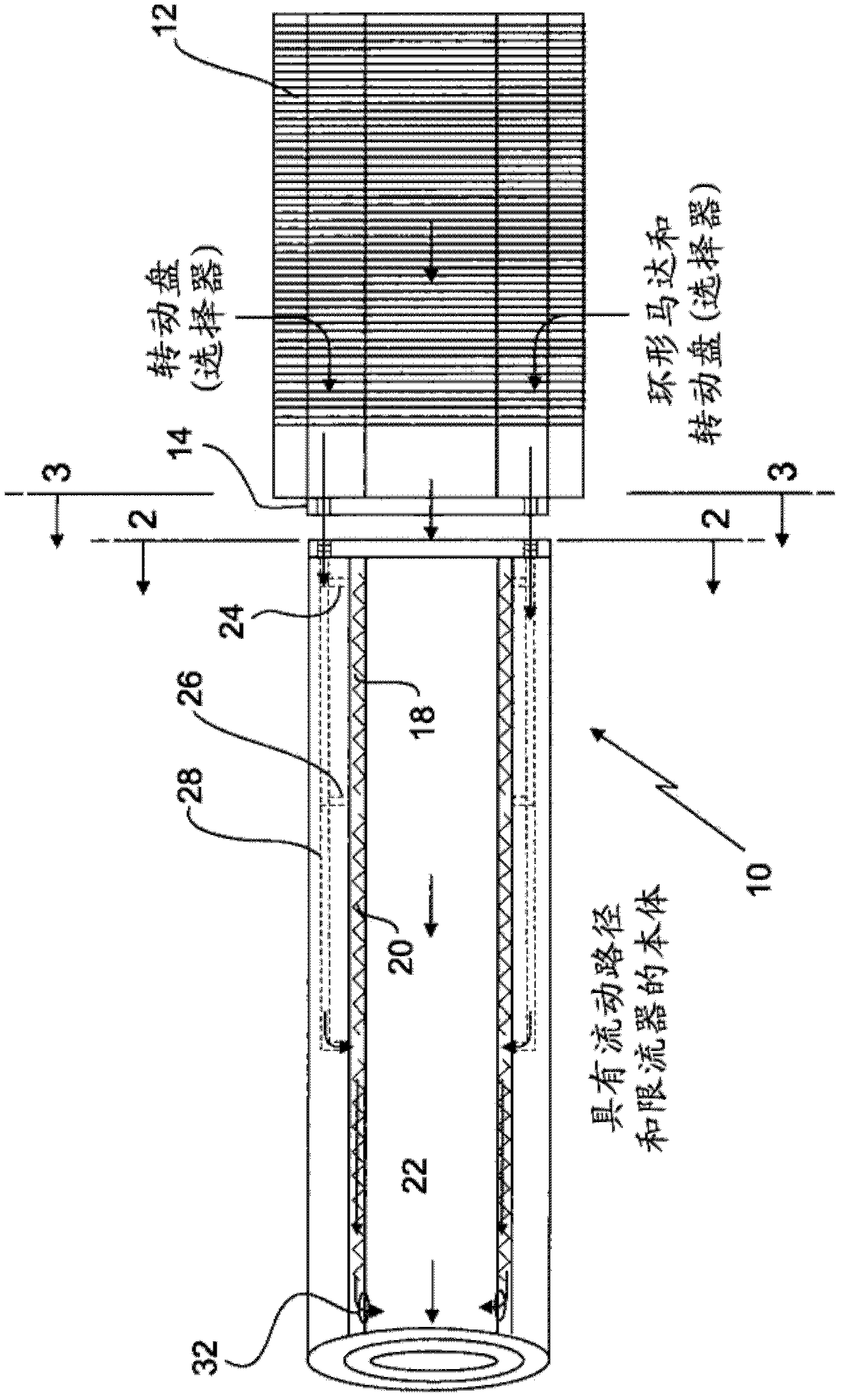
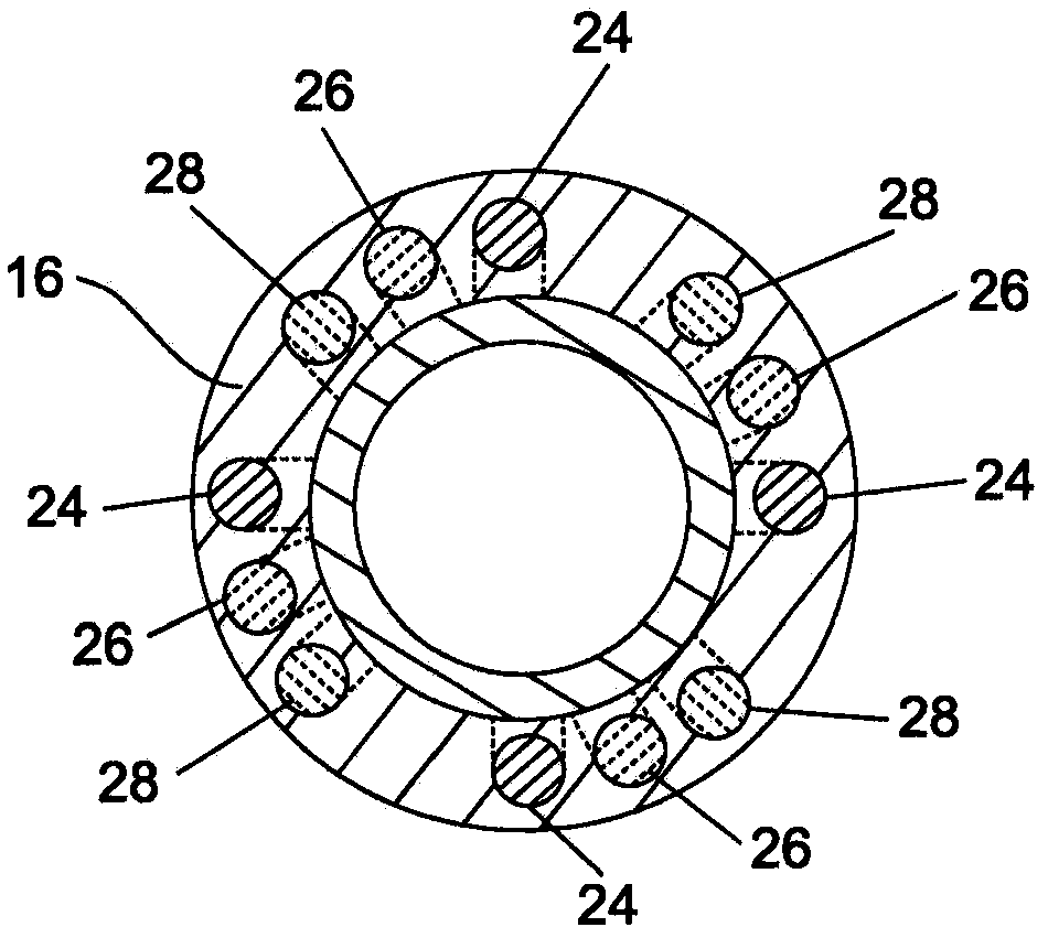
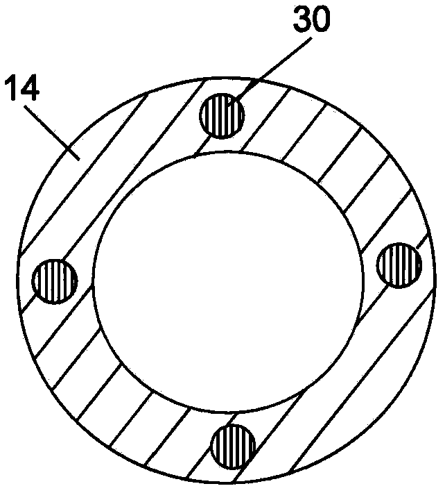
[0017] see figure 1 , a configuration 10 is schematically illustrated as comprising a screen section 12, a selector 14, and a body 16 comprising one or more flow restrictors 18, 20, 22 arranged in series (by way of example only; not limitation ). The body also includes a plurality of flow channels 24 , 26 , 28 (again by way of example; not limitation), which, in one embodiment, are grouped around the body 16 as shown. It should be understood that for functional diversity as taught herein, the number of restrictors need only be multiple (of this type of embodiment); pass" or "truncated", then its number needs to be only one. There is no upper limit to the number of flow restrictors that can be used, other than practical factors related to available space, length of tool required, or reasonably practicable for a given formation length. For reasons that will become clearer below, the number of flow channels in each set of flow channels is provided to match the number of flow r...


PUM


Abstract

A remotely controllable flow control configuration including a body; one or more flow restrictors disposed in the body; and a selector fluidly connected with the body and capable of supplying or denying fluid to one or more of the one or more flow restrictors and method.

Description

[0001] Cross References to Related Applications [0002] This invention contains subject matter related to subject matter of a co-pending application assigned to the same assignee as the present application, Baker Hughes Company of Houston, Texas, USA. The applications listed below are hereby incorporated by reference in their entirety. [0003] The U.S. patent application titled "REMOTELY CONTROLLABLE MANIFOLD" filed on July 2, 2009, with agency docket number 274-49269-US (BAO0340US). Background technique [0004] In a fluid flow system, a balance of fluid flow characteristics is necessary in order to optimize the system. An example of this is in the downhole drilling and completion industry where fluids flowing from or out of a subterranean formation into a wellbore are subjected to fingering due to the formation's varying permeability and frictional pressure drop. These devices, which have traditionally been attempted to control flow characteristics, are known in the art ...

Claims


Application Information

Patent Timeline
Patent Type & Authority Applications(China)
IPC IPC(8): E21B34/10E21B34/12
CPCE21B34/06E21B34/066E21B43/12Y10T137/86734Y10T137/87249
Inventor R·蒂拉多P·兰詹
Owner BAKER HUGHES INC
Why Eureka
Try Eureka