injector

A technology of injectors and nozzles, applied in the direction of machines/engines, drive pumps, mechanical equipment, etc., can solve problems such as deterioration of engine exhaust emissions, increased engine oil consumption, and changes in air-fuel ratio, so as to reduce flow deviation and suppress return The effect of reducing the amount and suppressing the change of flow characteristics

Active Publication Date: 2017-07-18
AISAN IND CO LTD +1
View PDF1 Cites 0 Cited by
  • Summary
  • Abstract
  • Description
  • Claims
  • Application Information

AI Technical Summary

Problems solved by technology

In this case, there is a concern that the engine oil is taken away from the crankcase of the engine together with the blow-by gas, and the consumption of the engine oil increases accordingly.
In addition, there is a possibility that the air-fuel ratio of the engine changes due to an increase in blow-by gas return amount and causes deterioration of exhaust emissions from the engine

Method used


Image

  • injector
  • injector
  • injector

Examples


Embodiment Construction

[0026] Hereinafter, an embodiment in which the injector of the present invention is applied to a blow-by gas returning device for an engine will be described in detail with reference to the drawings.

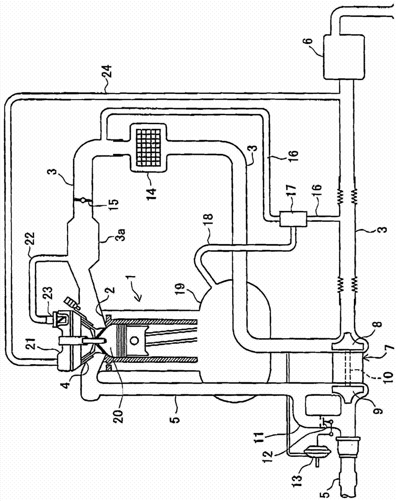
[0027] figure 1 In , the engine system including the blow-by gas returning device according to the present embodiment is shown by a schematic configuration diagram. The engine system includes a reciprocating engine 1 . The intake port 2 of the engine 1 is connected to the intake passage 3 , and the exhaust port 4 is connected to the exhaust passage 5 . An air filter 6 is provided at the inlet of the intake passage 3 . A supercharger 7 for boosting the intake air in the intake passage 3 is provided between the exhaust passage 5 and the portion downstream of the air cleaner 6 of the intake passage 3 .

[0028] The supercharger 7 includes a compressor 8 arranged in the intake passage 3 , a turbine 9 arranged in the exhaust passage 5 , and a rotary shaft 10 connecting the compres...


PUM


Abstract

An ejector includes: a decompression chamber in an outer pipe on an air entrance side; a throat in the outer pipe on an air exit side; a nozzle in the outer pipe on the air entrance side, the nozzle having a leading end portion placed in a decompression chamber to inject air; and a suction port in the decompression chamber to suck blow-by gas into the decompression chamber. The air injected from the nozzle generates negative pressure in the decompression chamber to suck in blow-by gas through the suction port, and the sucked gas is discharged together with air through a throat. The valve in the nozzle includes a valve seat, a valve element, and a spring to press the valve element in a direction to separate from the valve seat. The valve element is formed with a bottom-closed cavity opening toward an upstream side of an air flow.

Description

technical field [0001] The present invention relates to an injector that generates a negative pressure by flowing a working fluid and causes a target fluid to flow by the action of the negative pressure. Background technique [0002] Conventionally, as such a technique, for example, a jet pump (ejector) used in a blow-by gas returning device described in Patent Document 1 below is known. The return device is provided in an engine having a supercharger in an intake passage, and is configured to return blow-by gas generated by the engine from the blow-by gas return passage to the engine via the intake passage. The return device includes a bypass passage connecting the upstream side and the downstream side of the supercharger in the intake passage, and an injector for generating negative pressure in the bypass passage. In addition, the outlet of the blow-by gas return passage is connected to the bypass passage via the injector. Therefore, when the supercharger operates, a pre...

Claims


Application Information

Patent Timeline
Patent Type & Authority Patents(China)
IPC IPC(8): F01M13/00
CPCF01M13/023F01M2013/026F02M25/06Y02T10/12F04D9/06
Inventor 洞江幸宏池田淳
Owner AISAN IND CO LTD
Why Eureka
Try Eureka