Masonry structure integrity reinforcing method

A kind of masonry structure and integral technology, applied in the direction of building components, building structure, building maintenance, etc., can solve the problems of affecting structural safety, poor shear resistance, bending resistance, building collapse, etc., to increase the weight of the structure, improve Anti-seismic performance, the effect of improving the anti-seismic ability

Active Publication Date: 2012-05-30
上海维固工程实业有限公司 +2
View PDF4 Cites 7 Cited by
  • Summary
  • Abstract
  • Description
  • Claims
  • Application Information

AI Technical Summary

Problems solved by technology

Although the masonry structure has its own unique advantages, under the action of an earthquake, the shortcomings of the masonry structure will be seriously exposed, and even affect the safety of life and property.
[0003] First of all, in the existing masonry structure, the number of buildings using prefabricated floor slabs is still very large. Due to their poor integrity, they are easy to fall off in an earthquake, which may cause the building to collapse.
Secondly, although the brick wall with masonry structure has good compressive performance, its shear and bending resistance are poor. Under the action of earthquake force, the wall itself is prone to cracks or damage, which affects structural safety.
The traditional reinforcement method of masonry structure is to reinforce the brick wall and the floor slab separately, which does not enhance the integrity of the brick wall and the floor slab

Method used


Image

  • Masonry structure integrity reinforcing method
  • Masonry structure integrity reinforcing method
  • Masonry structure integrity reinforcing method

Examples


Embodiment Construction

[0019] In order to make the technical means, creative features, objectives and effects of the present invention easy to understand, the present invention will be further described below in conjunction with the accompanying drawings.

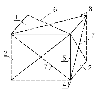
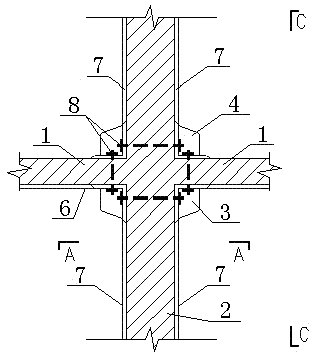
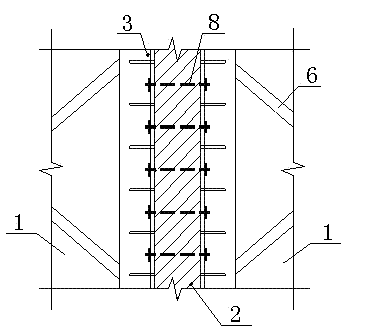
[0020] The integral reinforcement method of masonry structure of the present invention is as figure 1 As shown, the end reinforcement is set at the junction of the floor 1 and the wall 2, the top of the wall is the upper reinforcement 3, the bottom of the wall is the lower reinforcement 4, and the wall end reinforcement 5 is set at the junction of the two walls. Bottom reinforcement 6 is arranged on the bottom surface, and bottom reinforcement 6 is cross-connected with upper reinforcement 3 , and wall reinforcement 7 is arranged on wall 2 , and wall reinforcement 7 is cross-connected with end reinforcements 3 and 4 . The upper reinforcement 3 is connected to the wall reinforcement 7 , the board bottom reinforcement 6 and the wall end reinforcemen...


PUM


Abstract

The invention discloses a masonry structure integrity reinforcing method. In the method, an end reinforcing member is arranged at the junction between a floor and a wall surface; an upper end reinforcing member is arranged at the top of the wall, and a lower end reinforcing member is arranged at the bottom of the wall; when a ring beam exists, the upper end reinforcing member is not necessary, and a wall end reinforcing member is arranged at the junction of two walls; when a constructional column exists, the wall end reinforcing member is not necessary, a plate bottom reinforcing member is arranged at the bottom surface of the floor and is in cross connection with the upper end reinforcing member, and a wall surface reinforcing member is arranged on the wall surface and is in cross connection with the end reinforcing member; the upper end reinforcing member is connected with the wall surface reinforcing member, the plate bottom reinforcing member and the wall end reinforcing member; the lower end reinforcing member is connected with the wall surface reinforcing member and the wall end reinforcing member; and the upper end reinforcing member, the lower end reinforcing member, the wall end reinforcing member, the wall surface reinforcing member and the plate bottom reinforcing member are connected in a whole. Compared with the traditional reinforcement, the reinforcement of the floor and the reinforcement of the wall surface are connected with each other, the structural integrity is better, and the construction is simple and convenient and free from the influence of ambient temperature.

Description

technical field [0001] The invention relates to the field of reinforcement of brick masonry structures, in particular to an integral reinforcement method for masonry structures. Background technique [0002] As a traditional building structure form, masonry structure still occupies a large number at present. Although the masonry structure has its own unique advantages, under the action of an earthquake, the shortcomings of the masonry structure will be seriously exposed, and even affect the safety of life and property. [0003] First of all, in the existing masonry structure, the number of buildings using prefabricated floor slabs is still very large. Due to its poor integrity, it is easy to fall off in an earthquake, which may cause the collapse of the building. Secondly, although the brick wall with masonry structure has good compressive performance, its shear and bending resistance are poor. Under the action of earthquake force, the wall itself is prone to cracks or dama...

Claims


Application Information

Patent Timeline
Patent Type & Authority Applications(China)
IPC IPC(8): E04G23/02E04B1/98
Inventor 陈明中黄坤耀李静徐继东陈维清
Owner 上海维固工程实业有限公司
Why Eureka
Try Eureka