
Centrifugal pump

A centrifugal pump and pump body technology, applied in the field of centrifugal pumps, can solve the problems of easy generation of vortex, large hump, unstable operation of centrifugal pump, etc., and achieve the effect of stable operation and small hump

Inactive Publication Date: 2012-05-30
SHANDONG SHUANGLUN
View PDF0 Cites 0 Cited by
  • Summary
  • Abstract
  • Description
  • Claims
  • Application Information

AI Technical Summary

Problems solved by technology

[0003] The technical problem solved by the present invention is to solve the problem that the liquid is prone to vortex at the inlet, the hump of the lift curve of the centrifugal pump is large, and the operation of the centrifugal pump is unstable. Centrifugal pump with small hump and stable operation head with small hump

Method used


Image

  • Centrifugal pump
  • Centrifugal pump
  • Centrifugal pump

Examples


Embodiment Construction

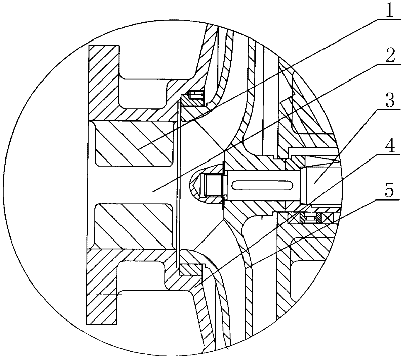
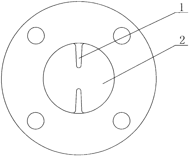
[0008] Such as figure 1 , figure 2 In the centrifugal pump shown, the pump body 4 is provided with a pump shaft 3, the pump shaft 3 is provided with an impeller 5, and the pump body 4 at the front end of the impeller 5 is provided with a suction chamber 2 corresponding to the suction inlet of the impeller, and the inner wall of the suction chamber 2 There is a baffle 1 on the top, the baffle 1 can prevent the liquid from rotating in the suction chamber 2, and prevent the impeller 5 from driving the liquid at the inlet to generate vortices. The liquid is not easy to generate vortices at the inlet. run smoothly. From figure 1 , figure 2 It can be seen from the figure that the inner wall of the suction chamber 2 is provided with two baffles, which have a good effect of preventing the liquid from rotating.


PUM


Abstract

The invention discloses a centrifugal pump. A pump shaft is arranged in a pump body, and is provided with an impeller; and the pump body at the front end of the impeller is provided with a suction chamber corresponding to the suction inlet of the impeller. The centrifugal pump is mainly structurally characterized in that: the inner wall of the suction chamber is provided with a separation blade. The inner wall of the suction chamber is provided with the separation blade which can be used for preventing a liquid from rotating in the suction chamber, so that the impeller is prevented from driving the liquid at an inlet to generate vortexes, the liquid is prevented from generating the vortexes easily at the inlet, and the centrifugal pump has a small hump on a head curve and runs stably.

Description

technical field [0001] The present invention relates to a liquid pump, in particular to a centrifugal pump. Background technique [0002] We know that the existing centrifugal pumps are provided with a pump shaft in the pump body, an impeller is arranged on the pump shaft, and a suction chamber is arranged on the pump body at the front end of the impeller corresponding to the suction inlet of the impeller, and the suction chamber is cylindrical. For centrifugal pumps, since the suction chamber is smooth and cylindrical, when the centrifugal pump is working, driven by the impeller, the liquid is prone to vortex at the inlet, the hump of the lift curve of the centrifugal pump is large, and the operation of the centrifugal pump is unstable. Contents of the invention [0003] The technical problem solved by the present invention is to solve the problem that the liquid is prone to vortex at the inlet, the hump of the lift curve of the centrifugal pump is large, and the operatio...

Claims


Application Information

Patent Timeline
Patent Type & Authority Applications(China)
IPC IPC(8): F04D1/00F04D29/00
Inventor 张学森李智于文超金小伟滕占刚
Owner SHANDONG SHUANGLUN
Learn More