
Anti-condensation electrical cabinet

An electrical cabinet and anti-condensation technology, applied in the field of electrical cabinets, can solve the problems of mold growth, creepage of electrical components, equipment fault tripping, etc., and achieve the effect of reducing condensation.

Active Publication Date: 2021-06-11
XINDIAN ELECTRIC GRP CO LTD
View PDF12 Cites 0 Cited by
  • Summary
  • Abstract
  • Description
  • Claims
  • Application Information

AI Technical Summary

Problems solved by technology

[0002] Generally, the internal space of the electrical cabinet is very compact. In the humid season, the air contains more water vapor, which will cause condensation on the insulating parts in the switch cabinet, the surface of the charged body or the local part of the switch cabinet, thereby breeding mold and accelerating the corrosion of metal conductors. , leading to oxidation of the contact surface, increased contact resistance, and reduced electrical insulation strength
And cause the temperature inside the cabinet to be lower than the temperature outside the cabinet, forming a temperature difference inside and outside the cabinet, the electrical equipment in the cabinet will generate heat after being powered on, the ambient temperature inside the cabinet is high, and the humid air rises. Water drops will form on the inner wall of the top plate of the power distribution cabinet, and even the entire top plate is covered with water drops
When the water droplets fall down, it will cause creepage and abnormal flashover discharge of electrical components caused by the insulation distance, cause a phase-to-phase short circuit, cause equipment fault tripping, and bring serious hidden dangers to the safe and stable operation of the equipment. Therefore, the present invention proposes An anti-condensation electrical cabinet is used to solve the above problems

Method used


Image

  • Anti-condensation electrical cabinet
  • Anti-condensation electrical cabinet
  • Anti-condensation electrical cabinet

Examples


Embodiment Construction

[0022] The following will clearly and completely describe the technical solutions in the embodiments of the present invention with reference to the accompanying drawings in the embodiments of the present invention. Obviously, the described embodiments are only some, not all, embodiments of the present invention. Based on the embodiments of the present invention, all other embodiments obtained by persons of ordinary skill in the art without making creative efforts belong to the protection scope of the present invention.

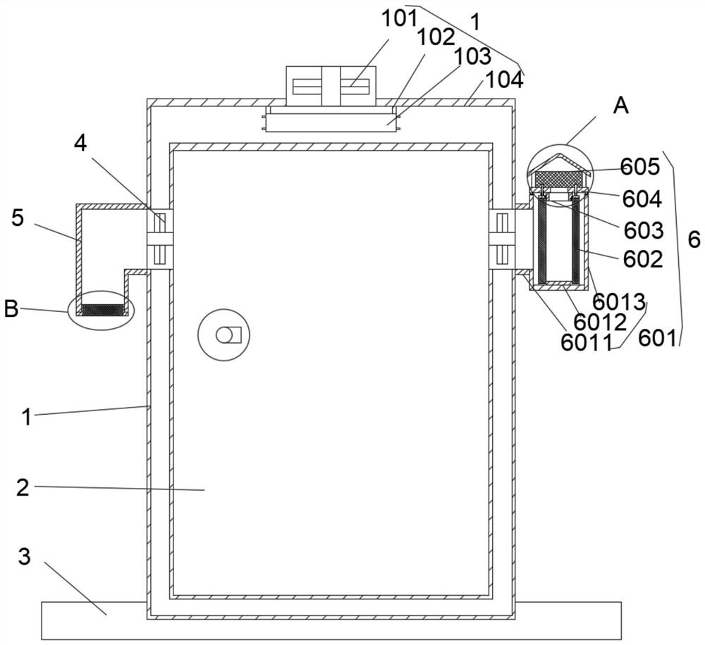
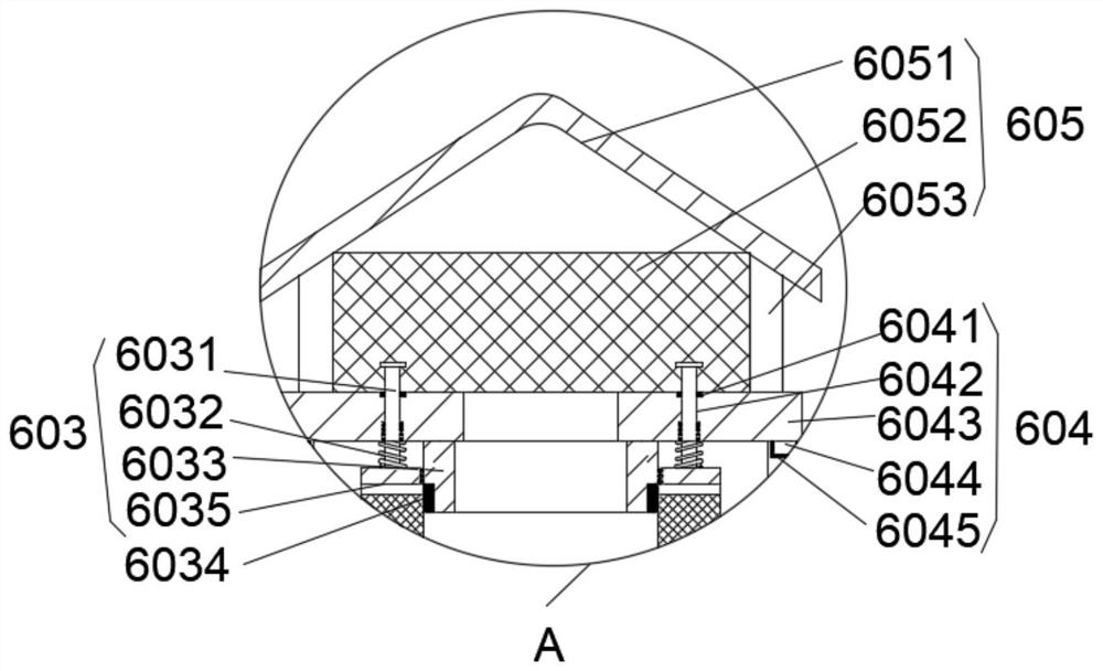
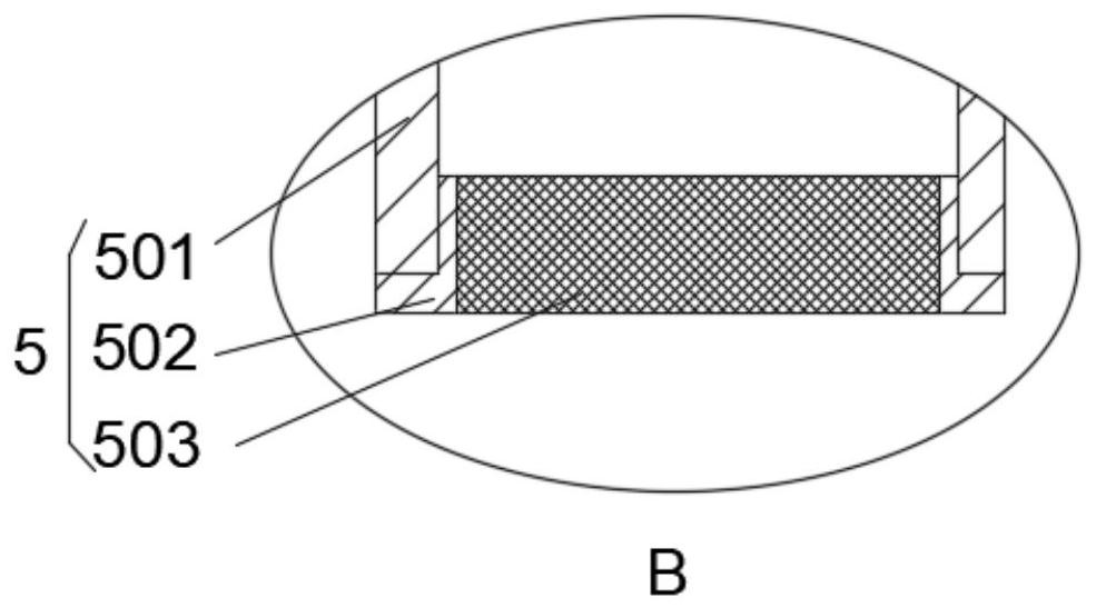
[0023] see Figure 1 to Figure 5 , the present invention provides a technical solution: an anti-condensation electrical cabinet, including an electrical cabinet box 1, a blocking door 2, a base 3, an exhaust fan 4, an air outlet mechanism 5, an air inlet mechanism 6, and an electrical cabinet box 1 is provided with a blocking door 2, the bottom of the electrical cabinet 1 is provided with a base 3, two sets of exhaust fans 4 are arranged symmetrically on both ...


PUM


Abstract

The invention relates to the technical field of electrical cabinets, in particular to an anti-condensation electrical cabinet which comprises an electrical cabinet box body, a blocking door, a base, exhaust fans, an air outlet mechanism and an air inlet mechanism, the blocking door is arranged on the electrical cabinet box body, the base is arranged at the bottom of the electrical cabinet box body, two sets of exhaust fans are symmetrically arranged on the two sides of the electrical cabinet box body, and one set of exhaust fans is connected with the air outlet mechanism; the two sets of exhaust fans operate at the same time, air flowing in the box body can be accelerated, on one hand, electronic components in the box body can be cooled, on the other hand, the interior of the box body and the outside are in a circulation state, the temperature difference is not too large, air circulates rapidly, humid air can flow out of the box body rapidly, and therefore condensation is greatly reduced, when the external temperature is rapidly reduced, the resistance wire heater is electrified to generate heat, and the heat is blown into the inner wall of the box body through the exhaust fan I, so that the temperature of the inner wall of the box body cannot be reduced along with the external temperature, and moisture is not easy to generate condensation on the inner wall of the box body.

Description

technical field [0001] The invention relates to the technical field of electrical cabinets, in particular to an anti-condensation electrical cabinet. Background technique [0002] Generally, the internal space of the electrical cabinet is very compact. In the humid season, the air contains more water vapor, which will cause condensation on the insulating parts in the switch cabinet, the surface of the charged body or the local part of the switch cabinet, thereby breeding mold and accelerating the corrosion of metal conductors. , leading to oxidation of the contact surface, increased contact resistance, and reduced electrical insulation strength. And cause the temperature inside the cabinet to be lower than the temperature outside the cabinet, forming a temperature difference inside and outside the cabinet, the electrical equipment in the cabinet will generate heat after being powered on, the ambient temperature inside the cabinet is high, and the humid air rises. Water drop...

Claims


Application Information

Patent Timeline
Patent Type & Authority Applications(China)
IPC IPC(8): H05K5/02H05K7/20
CPCH05K7/20136H05K7/20181H05K5/0217
Inventor 史鸿枭
Owner XINDIAN ELECTRIC GRP CO LTD
Learn More