Anti-vibration device

A technology for vibration isolation and installation of components, which is used in power plants, jet propulsion devices, internal combustion propulsion devices, etc. It can solve the problems of limited load resistance, limited spring tuning freedom, and difficulty in protruding from large heights, and achieve excellent load resistance. performance, sufficient durability

Active Publication Date: 2012-05-30
SUMITOMO RIKO CO LTD
View PDF8 Cites 7 Cited by
  • Summary
  • Abstract
  • Description
  • Claims
  • Application Information

AI Technical Summary

Problems solved by technology

[0004] However, it is difficult to set a large protrusion height in the convex portion formed by bending by such a press, and the achievable load resistance is limited.
In addition, in the width direction of the second mounting member, since there are no protrusions for supporting the rubber elastic body of the main body, it is difficult to ensure the load resistance of the rubber elastic body of the main body, and the degree of freedom in tuning the spring constant is also limited.

Method used


Image

  • Anti-vibration device
  • Anti-vibration device
  • Anti-vibration device

Examples


Embodiment Construction

[0041] Hereinafter, embodiments of the present invention will be described with reference to the drawings.

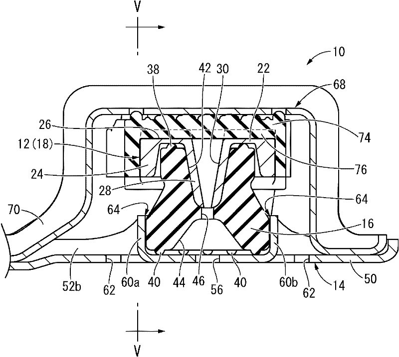
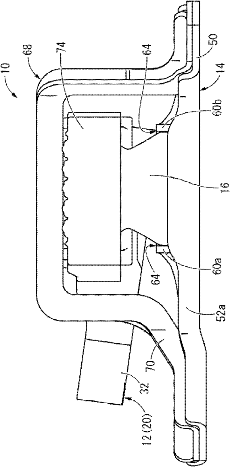
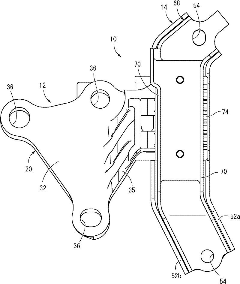
[0042] exist Figure 1 to Figure 5 In the figure, an engine mount 10 for an automobile is shown as one embodiment of a vibration isolating device having a structure based on the present invention. The engine mount 10 has a structure in which a first mounting member 12 and a second mounting member 14 opposed to each other in the axial direction are connected by a main body rubber elastic body 16 disposed between opposing surfaces of the mounting members 12 , 14 . Furthermore, the first mounting member 12 is mounted to a not-shown power component, and the second mounting member 14 is mounted to a not-shown vehicle body, thereby supporting the power component by vibration isolation of the vehicle body. In addition, in Figure 1 to Figure 5 In , the engine mount 10 in a single state before being mounted on a vehicle is shown. In addition, in the following description, th...


PUM


Abstract

Provided is an anti-vibration device comprising a novel structure which can position a main body rubber elastic part in either the width direction or the length direction of a second attachment member, and which can also achieve excellent load bearing resistance and durability. An anti-vibration device having a non-bonding structure in which a first attachment member and a second attachment member are arranged opposing each other and are linked by a main body rubber elastic part (16), wherein the second attachment member (14) has a groove shape provided with a bottom wall part (50) and a pairof sidewall parts (52a, 52b), portions of the bottom wall part (50) are cut and bent upward to form a pair of vertical wall parts (60a, 60b), and the main body rubber elastic part (16) is fitted in anon-bonding manner into a region enclosed by the pair of sidewall parts (52a, 52b),and the pair of vertical wall parts (60a, 60b). In addition, the outer peripheral surface of the main body rubber elastic part (16) is inwardly spaced apart from upper edge parts (64) and lateral edge parts (66) of the pair of vertical wall parts (60a, 60b) in the length direction.

Description

technical field [0001] The present invention relates to a vibration isolating device preferably used in, for example, an engine mount of an automobile or the like. Background technique [0002] Conventionally, a vibration isolator is known that is interposed between members constituting a vibration transmission system to isolate and connect these members, and application of the vibration isolator to an engine mount of an automobile or the like has been studied. The vibration isolator has a structure in which a first mounting member and a second mounting member mounted to one of the members constituting the vibration transmission system are elastically connected by a main body rubber elastic body. For example, the vibration isolator described in Japanese Patent Application Laid-Open No. 2006-177544 (Patent Document 1) has this structure, and has a structure in which a first mounting member and a second mounting member having a long plate shape are spaced apart from each other...

Claims


Application Information

Patent Timeline
Patent Type & Authority Applications(China)
IPC IPC(8): F16F15/08B60K5/12F16F1/36
CPCF16F1/376F16F1/373
Inventor 赤佐彰治井上智也纪
Owner SUMITOMO RIKO CO LTD
Why Eureka
Try Eureka