

Communication system and communication control method
A technology of communication system and communication control, which is applied in the field of communication system to achieve the effect of optimizing the use of resources and ensuring cost advantages
- Summary
- Abstract
- Description
- Claims
- Application Information
AI Technical Summary
Problems solved by technology
Method used
Image

Examples
Embodiment approach 1
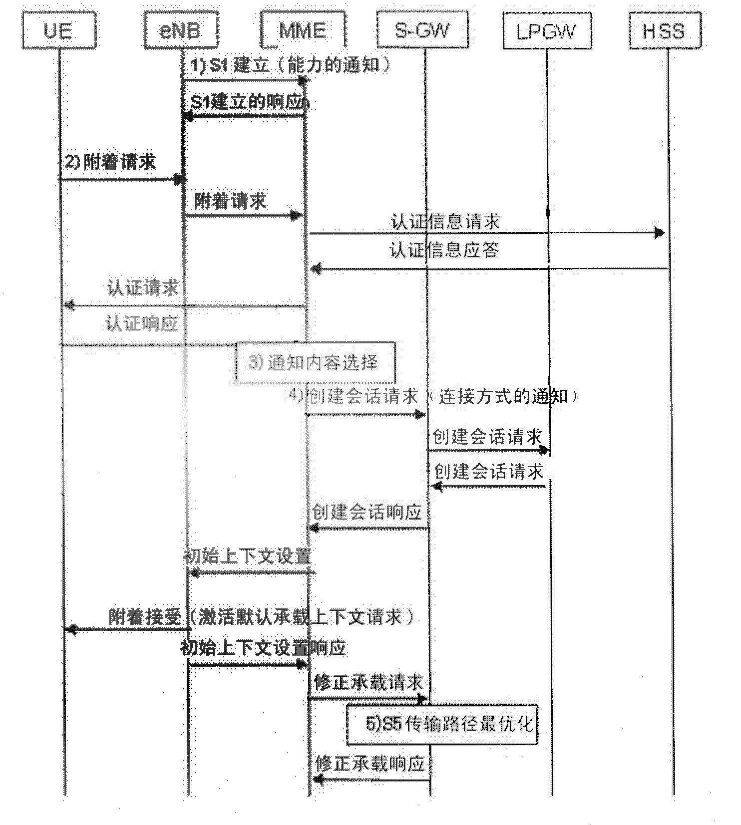
[0050] image 3 It is a diagram showing the optimization procedure of the S5 transmission path in one embodiment of the present invention. refer to image 3 , which shows the S1 setup (S1 Setup) process and the process of the terminal registering with the network and establishing a transmission path.
[0051] 1) Capability notification when connection is established
[0052] The eNB establishes the connection through the S1 setup (S1Setup) that is the interface between the eNB and the MME, and adds the capability of whether the radio access network can directly forward packets to the external network to the normal signal, and Notify to MME (capability notification).
[0053] The MME that has received the notification reserves the capabilities of the eNB. A response to S1 Setup (S1 Setup Response) is sent from the MME to the eNB.
[0054] 2) Attach Request (Attach Request)
[0055] Sends a request (attach request) from a terminal (UE) to register with a network and establ...
Embodiment approach 2
[0071] Next, a second embodiment of the present invention will be described. Figure 6 The state of the transmission path when the terminal (UE) registers (attaches) with the network and secures the transmission path is shown in an idle state (idle state: non-communication state). The resources of the wireless transmission path and the S1 transmission path are released at this time. In addition, in the idle state, the UE does not transmit and receive packets in the power saving state. In idle state, the context of the terminal (UE) is not stored in the eNB. However, even in this case, although communication packets do not flow on the S5 transmission path, resources are secured, and optimal use of the resources is required.
[0072] Figure 7 It shows the release procedure of the S1 transmission path performed in the idle state (non-communication state) of the UE when the GTPv2 (GPRS (General Packet Radio Service) tunneling protocol) protocol is applied to the S5 interface. ...
Embodiment approach 3
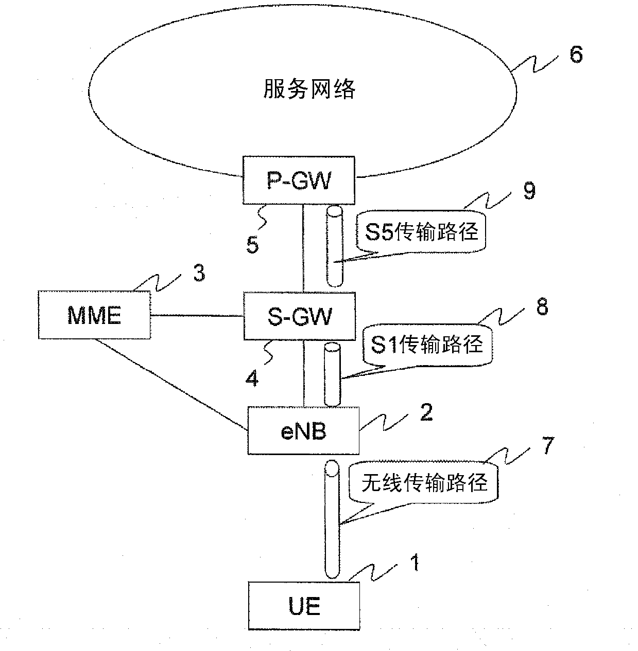
[0089] Next, a third embodiment of the present invention will be described. Figure 9 It is a diagram for explaining the network configuration to which the third embodiment of the present invention is applied. exist Figure 9 The connection network configuration of 3G (third generation) mobile communication is shown in . In the case where the terminal (UE) 1' communicates, such as Figure 9As shown, the radio transmission path 14, the Iu transmission path 15 between the RNC (Radio Network Controller: radio network control device) / NB (NodeB) and the SGSN (Serving GPRS Support Node), and the Iu transmission path 15 between the SGSN and the GGSN (Gateway GPRS Gn transmission path 16 between supporting nodes), the terminal (UE) 1 can communicate with the service network 6' as an external network. At this time, each device secures transmission path resources in order to ensure communication quality such as QoS (Quality of Service) according to the provided service.
[0090] ref...
PUM
 Abstract
Description
Claims
Application Information