
Circulating air exchange fan system

A fan system and fan technology, applied in the field of ventilation systems, can solve the problems of increasing the number of pipelines, increasing production costs, time-consuming and labor-intensive installation, etc., and achieve the effects of reliable working performance, low cost, and easy operation

Inactive Publication Date: 2012-06-06
XIAN ZHONGKEMAITE ELECTRONICS TECH EQUIP
View PDF3 Cites 6 Cited by
  • Summary
  • Abstract
  • Description
  • Claims
  • Application Information

AI Technical Summary

Problems solved by technology

The indoor circulation and ventilation systems used in many aging houses need to rely on two sets of fans, namely the circulation fan and the ventilation fan, which not only increase the number of indoor heat sources, complicate the operation, but also increase the number of pipelines, which is time-consuming and laborious to install, which is very inconvenient , while increasing production costs

Method used


Image

  • Circulating air exchange fan system
  • Circulating air exchange fan system
  • Circulating air exchange fan system

Examples


Embodiment Construction

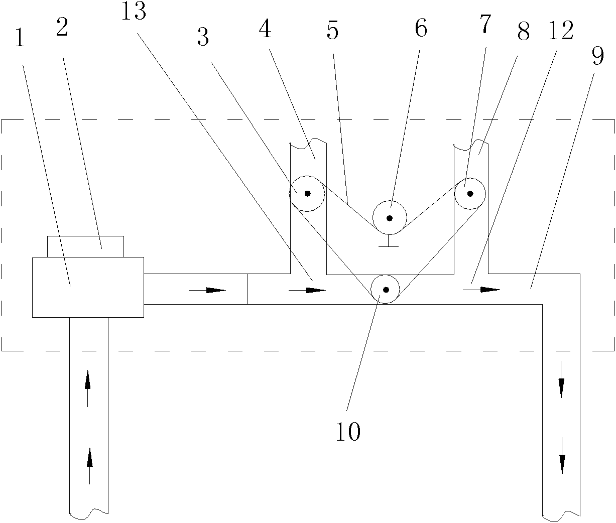
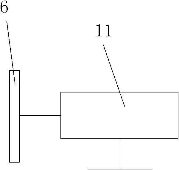
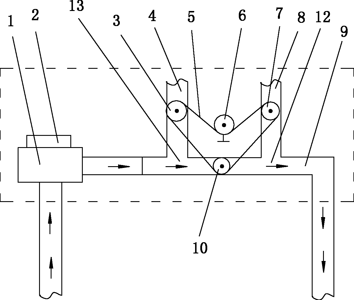
[0023] Such as figure 1 , figure 2 Shown, the present invention comprises air inlet pipe 8 and air outlet pipe 4, the air inlet 12 that joins with air inlet pipe 8 and air outlet pipe 4 respectively and air outlet 13 and is installed on the air inlet pipe 8 and air outlet pipe 4 respectively. The inlet pipe valve 7 and the outlet pipe valve 3, the inlet pipe 8 and the air inlet 12 are connected to form an inlet pipeline, the outlet pipe 4 and the outlet 13 are connected to form an outlet pipeline, and the inlet pipeline and the outlet pipeline form a ventilation Channel, the fan 1 driven by the fan motor 2 is installed on the outlet pipeline. A circulation passage 9 is connected between the air inlet 12 and the air outlet 13 or between the air inlet pipe 8 and the air outlet pipe 4, and the air inlet 12, the circulation passage 9 and the air outlet 13 are communicated to form a circulation passage, so A circulation channel valve 10 is installed on the circulation channel 9,...


PUM


Abstract

The invention discloses a circulating air exchange fan system, which comprises an air feeding pipe, an air discharging pipe, an air feeding port, an air discharging port, an air feeding pipe valve and an air discharging pipe valve. The air feeding port and the air discharging port are respectively connected with the air feeding pipe and the air discharging pipe, the air feeding pipe and the air feeding port form an air feeding pipeline, the air discharging pipe and the air discharging port form an air discharging pipeline, and the air feeding pipeline and the air discharging pipeline form an air exchange channel; a circulating air duct is connected between the air feeding port and the air discharging port or between the air feeding pipe and the air discharging pipe, the air feeding port, the circulating channel and the air discharging port form a circulating channel, and the circulating channel is provided with a circulating channel valve; and the air feeding pipe valve, the air discharging pipe valve and the circulating channel valve are driven by a motor and are connected with the power output shaft of the motor through a linkage mechanism, and the linkage mechanism adopts a sprocket / chain linkage mechanism. The circulating air exchange fan system has a simple structure and good use effects and can be operated easily, and the switching of indoor air circulation and indoor-outdoor air exchange of the high-temperature aging room can be realized through one set of air exchange mechanism.

Description

technical field [0001] The invention relates to a ventilation system, in particular to a circulating ventilation blower system. Background technique [0002] The aging room, also known as the burn-in room, is a simulation room for high-performance electronic products (such as computer machines, monitors, terminals, automotive electronics, power supplies, motherboards, monitors, and switching chargers, etc.). A high-temperature, harsh test environment equipment is an important experimental equipment to improve product stability and reliability. This equipment has been widely used in power electronics, computers, communications, biopharmaceuticals and other fields. [0003] The indoor circulation and ventilation function of the aging room is an important link to ensure the smooth progress of production. The indoor circulation and ventilation systems used in many aging houses need to rely on two sets of fans, namely the circulation fan and the ventilation fan, which not only i...

Claims


Application Information

Patent Timeline
Patent Type & Authority Applications(China)
IPC IPC(8): F24F7/06
Inventor 张国琦曹捷麻树波
Owner XIAN ZHONGKEMAITE ELECTRONICS TECH EQUIP
Learn More