Wire feeding reduction gearbox

A reduction box and wire feeding technology, which is applied in the field of spring equipment manufacturing and processing, can solve the problems of decreased positioning accuracy of the wire feeding wheel, troublesome adjustment of the wire feeding wheel, and inconvenient adjustment operation, so as to improve production efficiency, reduce work burden, Avoid intermittently added effects

Active Publication Date: 2012-06-13
ZHEJIANG OMNIPOTENT SPRING MACHINE
View PDF5 Cites 1 Cited by
  • Summary
  • Abstract
  • Description
  • Claims
  • Application Information

AI Technical Summary

Problems solved by technology

[0003] There are many disadvantages in the wire feeding box with this structure. First of all, it is troublesome to adjust the wire feeding wheel during the spring coiling process. It needs manual running back and forth to adjust, which brings great inconvenience to the production work.
Secondly, the adjustment operation is inconvenient. Too frequent thread adjustment of the wire feeding shaft leads to wear and loosening, which reduces the positioning accuracy of the wire feeding wheel and affects the quality of the coil spring.

Method used


Image

  • Wire feeding reduction gearbox
  • Wire feeding reduction gearbox
  • Wire feeding reduction gearbox

Examples


Embodiment Construction

[0026] combine Figure 1 to Figure 5 , the preferred embodiments of the present invention will be described in further detail.

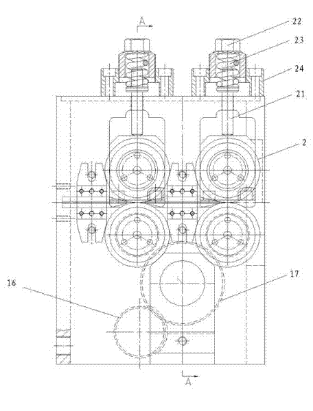
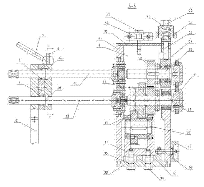
[0027] A wire-feeding reduction box, including a wire-feeding shaft 1 and a wire-feeding wheel 2. In this embodiment, there are four wire-feeding shafts 1, which are divided into two groups and arranged up and down. The upper one is the upper feeding shaft 11, and the lower one is the lower feeding shaft 12 , the upper wire feeding shaft 11 and the lower wire feeding shaft 12 are all worn and supported on the wire feeding box body 3, and the end position stretches out of the wire feeding box body 3, and the wire feeding wheel 2 is installed.

[0028] The tails of the upper wire feed shaft 11 and the lower wire feed shaft 12 are respectively connected to the upper wire feed adjustment shaft 71 and the lower wire feed adjustment shaft 72, and a fixing mechanism is installed on the upper wire feed adjustment shaft 71 and the lower wire feed adjustment s...


PUM


Abstract

The invention discloses a wire feeding reduction gearbox, which comprises a transmission mechanism, wire feeding shafts and wire feeding regulating shafts, wherein the wire feeding shafts are erected horizontally, one end of each of the wire feeding shafts is connected with one wire feeding regulating shaft while the other end of each of the wire feeding shafts is provided with a wire feeding wheel, the transmission mechanism transmits power to the wire feeding shafts, and fixing mechanisms used for axially positioning the wire feeding regulating shafts are mounted on the wire feeding regulating shafts. The wire feeding reduction gearbox is simple and convenient in operation, high in precision and long in service life and operators do not need to run back and forth to regulate the wire feeding reduction gearbox.

Description

technical field [0001] The invention relates to the technical field of spring equipment production, manufacturing and processing, in particular to a wire-feeding reduction box in a spring coiling machine. Background technique [0002] In the existing spring coiling machine, the wire feeding box is installed on the back side of the spring coiling machine panel, the wire feeding adjusting shaft is placed in a vertical state, and the wire feeding wheel is placed in a horizontal state. When the axial position of the wire feeding shaft needs to be adjusted during the spring coiling process, the operator needs to go around the back of the device, and then rotate the threaded structure at the bottom of the wire feeding shaft to adjust the axis position of the wire feeding shaft. [0003] There are many disadvantages in the wire feeding box with such a structure. Firstly, in the process of coiling the spring, it is troublesome to adjust the wire feeding wheel, and it needs to be man...

Claims


Application Information

Patent Timeline
IPC IPC(8): B21F23/00
Inventor 金苗兴叶景春
Owner ZHEJIANG OMNIPOTENT SPRING MACHINE
Why Eureka
Try Eureka