
Arc striking control method for gas metal arc welding and welding machine therefor

A technology of molten electrode gas and control method, which is applied in the direction of arc welding equipment, manufacturing tools, welding equipment, etc., and can solve problems such as prolonging welding time, wire collapse, and affecting welding quality

Active Publication Date: 2012-06-13
PANASONIC WELDING SYST TANGSHAN
View PDF6 Cites 11 Cited by
  • Summary
  • Abstract
  • Description
  • Claims
  • Application Information

AI Technical Summary

Problems solved by technology

This type of welding requires fast arc ignition, and a long arc ignition time will lengthen the welding time each time, resulting in a decrease in welding efficiency; or shorten the actual welding time each time, resulting in unqualified welding quality
[0004] 2) The slow wire feeding method has been adopted from the start of the welding switch to the ignition of the arc, which further increases the arc ignition time
[0005] 3) When the welding wire contacts the welding workpiece before the arc is started, it will cause the arc to be unsmooth, and if it is not handled properly, it will affect the welding quality
In this case, the welding wire is still fed at the standard wire feed speed after the arc is broken, and the standard wire feed speed is faster, so wire breakage will occur

Method used


Image

  • Arc striking control method for gas metal arc welding and welding machine therefor
  • Arc striking control method for gas metal arc welding and welding machine therefor
  • Arc striking control method for gas metal arc welding and welding machine therefor

Examples


Embodiment Construction

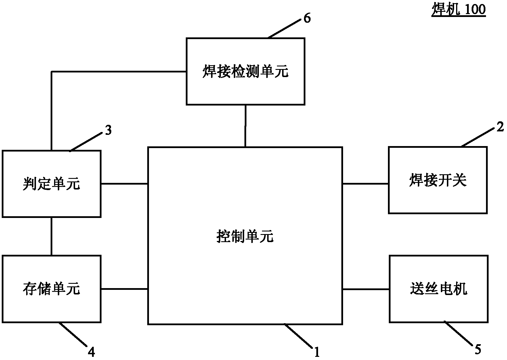
[0016] figure 1 It is a schematic diagram of the gas-shielded arc welding machine of the present invention. like figure 1 As shown, the welding machine 100 includes: a control unit 1 , a welding switch 2 , a determination unit 3 , a storage unit 4 , a wire feeding motor 5 and a welding detection unit 6 . The control unit 1 is respectively connected with the welding switch 2 , the determination unit 3 , the storage unit 4 , the wire feeding motor 5 and the welding detection unit 6 , and is used for controlling the arc striking operation of the welding machine 100 . The determination unit 3 is connected to the storage unit 4 and the welding detection unit 6 respectively, and is used to determine whether to proceed to the next step according to the parameters pre-stored in the storage unit 4 and the parameters detected by the welding detection unit 6 . The storage unit 4 is used to store preset parameters, including: welding stop time limit L1, first time limit L2, first slow...


PUM


Abstract

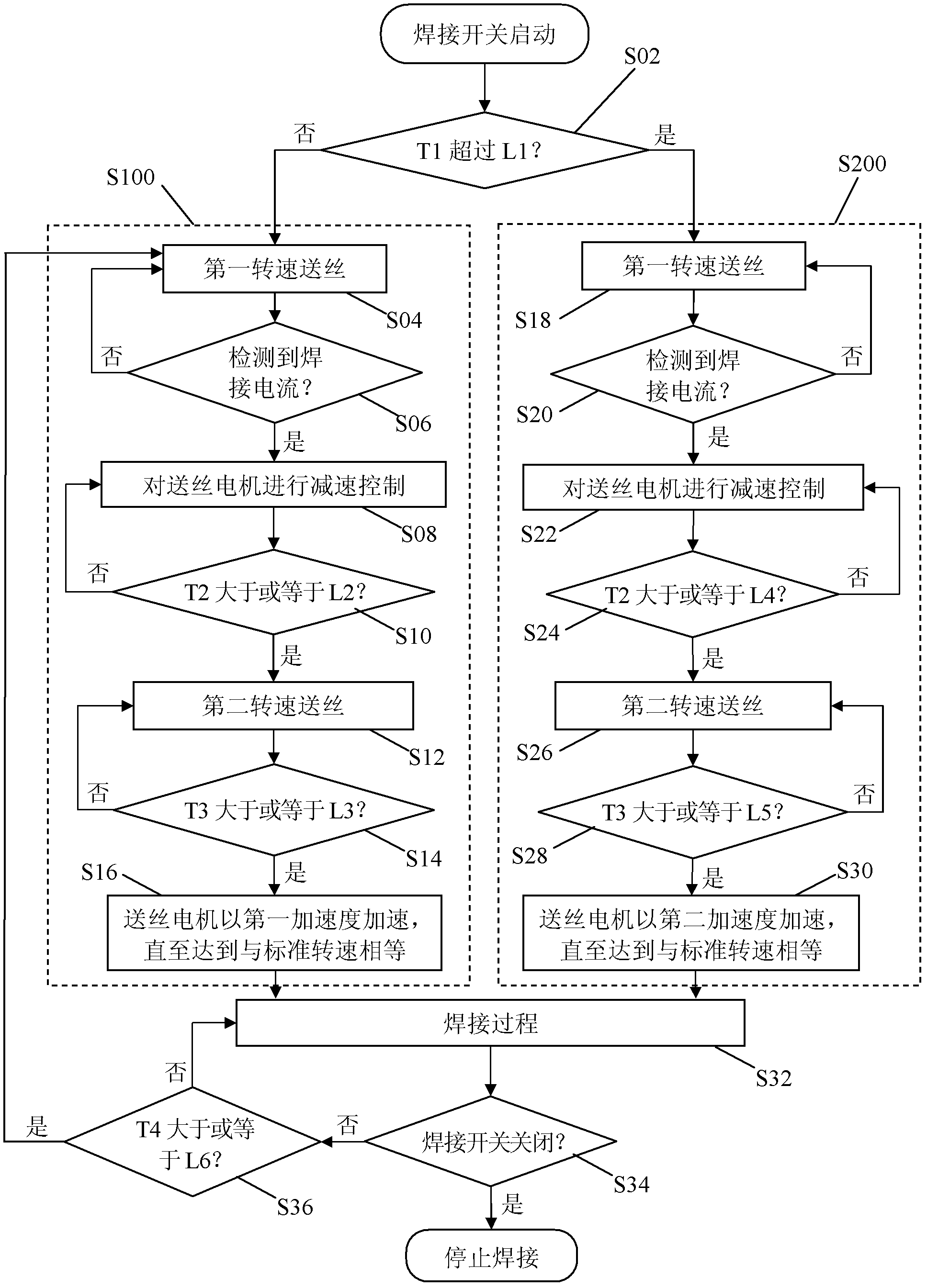
The invention discloses an arc striking control method for gas metal arc welding. A welding machine for implementing the arc striking control method comprises a control unit, a welding switch, a judging unit, a storage unit and a wire feeding motor, wherein the control unit controls a rotation speed of the wire feeding motor. The arc striking control method is characterized by comprising the following steps that: when the welding switch is turned on, the judging unit acquires welding stop time duration T1 before the welding switch is turned on, judges whether the time duration T1 is greater than a welding stop time limit L1 which is pre-stored in the storage unit, and transmits a judging result to the control unit; the control unit controls the welding machine to perform a first arc striking mode operation if the time duration T1 is less than or equal to the time limit L1; and the control unit controls the welding machine to perform a second arc striking mode operation which is different from the first arc striking mode operation if the time duration T1 is greater than the time limit L1.

Description

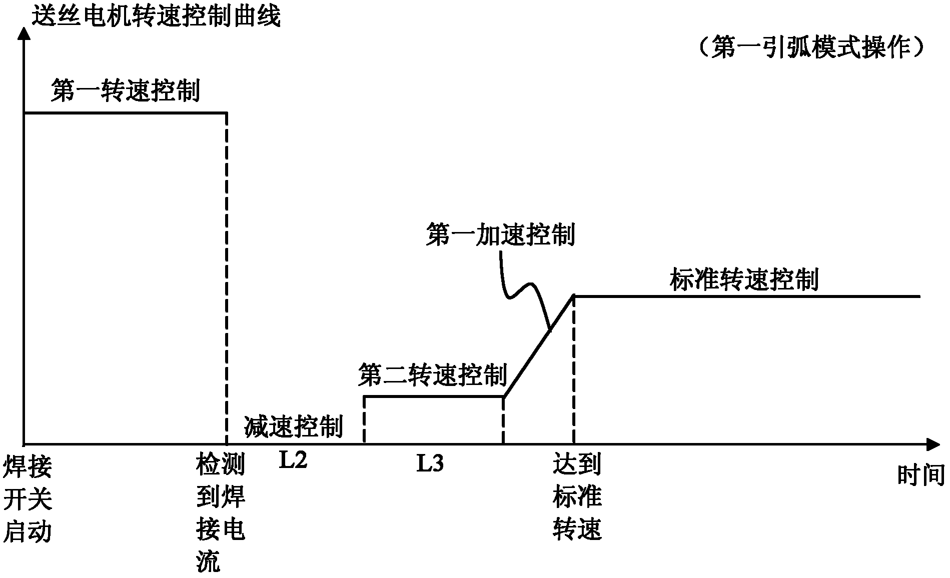
technical field [0001] The invention relates to the arc-starting control technology of arc welding, in particular to the arc-starting control technology of melting electrode gas shielded arc welding. Background technique [0002] At present, the commonly used arc ignition control methods for MIGA welding are, for example, Figure 5 As shown, the slow wire feeding method is adopted at the beginning of arc ignition, that is, the wire feeding speed is lower than the standard wire feeding speed during welding, and the wire feeding speed is increased to the standard wire feeding speed after the arc is ignited, so that To achieve smooth arc start. However, this arc striking control method has the following problems: [0003] 1) The same arc ignition control method is adopted for each arc ignition, regardless of the length of welding stop before arc ignition. In fact, for the case where the welding stop time before arc ignition is relatively short (for example, short-term arc int...

Claims


Application Information

Patent Timeline
Patent Type & Authority Applications(China)
IPC IPC(8): B23K9/067B23K9/173
Inventor 苏宪东张立伟郭怀书
Owner PANASONIC WELDING SYST TANGSHAN
Learn More