

Four-groove gang drill
A technology of auxiliary discharge and chip removal groove, applied in the field of four-groove drilling, can solve the problems of affecting the processing quality, easy drilling deviation, inaccurate positioning, etc. Effect
- Summary
- Abstract
- Description
- Claims
- Application Information
AI Technical Summary
Problems solved by technology
Method used
Image

Examples
Embodiment Construction
[0014] The present invention will be further described below in conjunction with accompanying drawing:
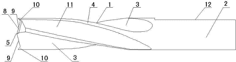
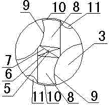
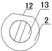
[0015] like figure 1 , figure 2 , image 3 As shown, the four flute row drill is composed of a cutting part 1 and a shank part 2 connected in sequence. The cutting part 1 is provided with two helical chip removal flutes 3, and the part between the helical chip removal flutes 3 forms a cutter body 4. A positioning tip 5 protrudes in the middle of the front end of the cutting part 1, and the positioning tip 5 is surrounded by four inclined positioning surfaces 6, and the edges where the four inclined positioning surfaces 6 intersect form a positioning edge 7, and the positioning tip 5 is symmetrically arranged outwardly. Two downward steep slopes 8, the slope 8 and the groove bottom of the spiral chip flute 3 form an end edge 9, and the end edge 9 and the outer peripheral surface of the cutting part 1 form two outer sharps 10. The body 4 is provided with a spiral auxiliar...
PUM
 Abstract
Description
Claims
Application Information